Memobus/modbus data table, Command data, D.9 memobus/modbus data table – Yaskawa Z1000U HVAC Matrix Bypass User Manual
Page 394
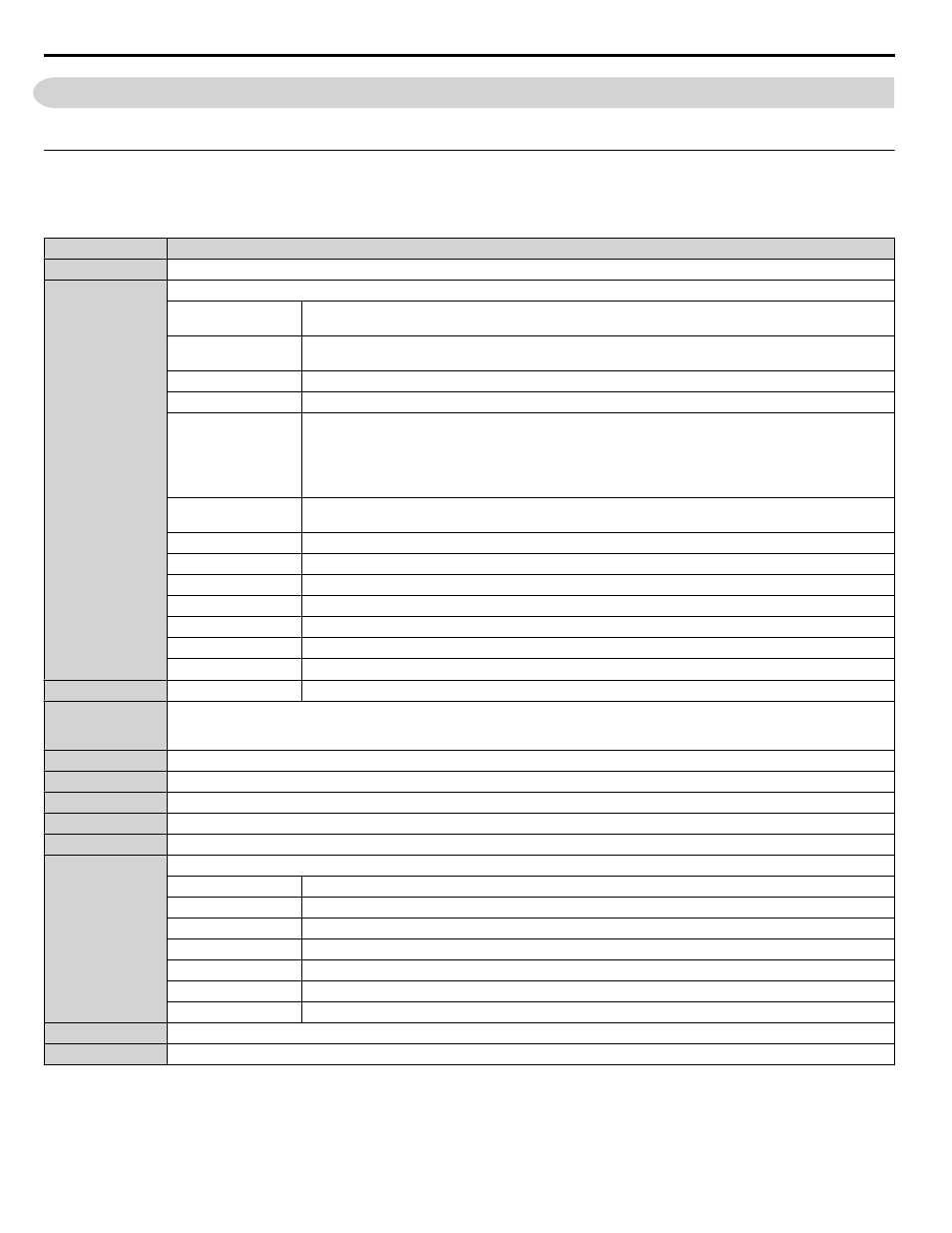
D.9 MEMOBUS/Modbus Data Table
The tables below list all MEMOBUS/Modbus data.
u
Command Data
It is possible to both read and write command data.
Note:
Bits that are not used should be set to 0. Refrain from writing to reserved registers.
Register No.
Contents
0000H
Reserved
0001H
Operation Commands and Multi-function Inputs
bit 0
H5-12 = 0: Forward Run Command (0 = Stop, 1 = Forward Run)
H5-12 = 1: Run Command (0 = Stop, 1 = Run)
bit 1
H5-12 = 0: Reverse Run Command (0 = Stop, 1 = Reverse Run)
H5-12 = 1: Forward/Reverse (0 = Forward, 1 = Reverse)
bit 2
Option Card External Fault (EF0)
bit 3
Fault Reset
bit 4
Multi-Function Input 1
Function is ComRef when H1-01 = 40 (Forward/Stop).
Note:
When the bit at ComCtrl is turned on, commands from MEMOBUS/Modbus
communications take control of the operation. However, when a communications option
card is connected, that option card is given priority.
bit 5
Multi-Function Input 2
Function is ComCtrl when H1-02 = 41 (Reverse/Stop).
bit 6
Multi-Function Input 3
bit 7
Multi-Function Input 4
bit 8
Multi-Function Input 5
bit 9
Multi-Function Input 6
bit A
Multi-Function Input 7
bit B
Multi-Function Input 8
bit C to F
Reserved
0002H
Frequency Reference Units are determined by parameter o1-03.
0003H
Output voltage gain/
Unit: 0.1%
Range: 20 (2.0%) to 2000 (200.0%), Default when power on: 1000 (100.0%)
0004H
Torque Reference/Torque Limit, 0.1% units, signed (Usable only if Torque Control is enabled)
0005H
Torque Compensation, 0.1% units, signed (Usable only if Torque Control is enabled)
0006H
PID Target, 0.01% units, signed
0007H
Analog Output Terminal FM Setting (10 V / 4000 H)
0008H
Analog Output Terminal AM Setting (10 V / 4000 H)
0009H
Settings for Multi-Function Digital Outputs
bit 0
Multi-Function Contact Output 1 (terminal M1-M2)
bit 1
Multi-Function Contact Output 2 (terminal M3-M4)
bit 2
Multi-Function Contact Output 3 (terminal MD-ME-MF)
bit 3 to 5
Reserved
bit 6
Enables the function in bit 7
bit 7
Fault Contact Output (terminal MA/MB-MC)
bit 8 to F
Reserved
000AH
Pulse Output Terminal MP Setting, 1 Hz units, Setting Range: 0 to 32000
000BH to 000EH
Reserved
D.9 MEMOBUS/Modbus Data Table
394
YASKAWA SIEP YAIZ1D 01A Z1000U HVAC MATRIX Drive Bypass Technical Manual