H4: analog outputs – Yaskawa Z1000U HVAC Matrix Bypass User Manual
Page 328
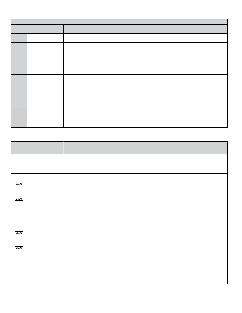
H3 Multi-Function Analog Input Settings
H3-oo
Setting
Function
LCD Display
Description
Page
6
DC Injection Braking
current
DC Brake Current
10 V = Drive rated current
7
Overtorque/undertorque
detection level
Torque Det Level
10 V = Drive rated current
8
Stall Prevention level
during run
Stall Prev Level
10 V = Drive rated current
9
Output frequency lower
limit level
Ref Lower Limit
10 V = E1-04 (maximum output frequency)
B
PID feedback
PID Feedback1
10 V = 100%
C
PID setpoint
PID Set Point
10 V = 100%
D
Frequency bias
Freq Ref Bias 2
10 V = E1-04 (maximum output frequency)
E
Motor temperature (PTC
input)
Motor PTC
10 V = 100%
F
Through mode
Not Used
Set this value when using the terminal in the pass-through mode.
16
Differential PID
feedback
PID Feedback 2
10 V = 100%
1F
HAND Reference
Hand Ref
Sets the frequency reference when in HAND Mode and parameter Z1-41, HAND
Speed Reference Selection, is set to 1 (Analog).
25
Secondary PI Setpoint
PI2 Setpoint
10 V = S3-02 (maximum output frequency)
26
Secondary PI Feedback PI2 Feedback
10 V = S3-02 (maximum output frequency)
u
H4: Analog Outputs
No.
(Addr.
Hex)
Name
LCD Display
Description
Values
Page
H4-01
(041D)
Multi-Function Analog
Output Terminal FM
Monitor Selection
Term FM FuncSel
Selects the data to be output through multi-function analog
output terminal FM.
Set the desired monitor parameter to the digits available in
Uo-oo.
For example, enter “103” for U1-03.
Default: 102
Range: 000 to
621
H4-02
(041E)
Multi-Function Analog
Output Terminal FM
Gain
Terminal FM Gain
Sets the signal level at terminal FM that is equal to 100% of the
selected monitor value.
Default: 100.0%
Min.: -999.9
Max.: 999.9
H4-03
(041F)
Multi-Function Analog
Output Terminal FM
Bias
Terminal FM Bias
Sets the signal level at terminal FM that is equal to 0% of the
selected monitor value.
Default: 0.0%
Min.: -999.9
Max.: 999.9
H4-04
(0420)
Multi-Function Analog
Output Terminal AM
Monitor Selection
Terminal AM Sel
Selects the data to be output through multi-function analog
output terminal AM.
Set the desired monitor parameter to the digits available in
Uo-oo.
For example, enter “103” for U1-03.
Default: 103
Range: 000 to
621
H4-05
(0421)
Multi-Function Analog
Output Terminal AM
Gain
Terminal AM Gain
Sets the signal level at terminal AM that is equal to 100% of
the selected monitor value.
Default: 50.0%
Min.: -999.9
Max.: 999.9
H4-06
(0422)
Multi-Function Analog
Output Terminal AM
Bias
Terminal AM Bias
Sets the signal level at terminal AM that is equal to 0% of the
selected monitor value.
Default: 0.0%
Min.: -999.9
Max.: 999.9
H4-07
(0423)
Multi-Function Analog
Output Terminal FM
Signal Level Selection
Term FM Lvl Sel
0-10 VDC
1: -10 +10 VDC
2: 4-20 mA
0: 0 to 10 V
1: -10 to +10 V
2: 4 to 20 mA
Default: 0
Range: 0 to 2
H4-08
(0424)
Multi-Function Analog
Output Terminal AM
Signal Level Selection
Term AM Lvl Sel
0-10 VDC
1: -10 +10 VDC
2: 4-20 mA
0: 0 to 10 V
1: -10 to +10 V
2: 4 to 20 mA
Default: 0
Range: 0 to 2
B.8 H Parameters: Multi-Function Terminals
328
YASKAWA SIEP YAIZ1D 01A Z1000U HVAC MATRIX Drive Bypass Technical Manual