Bypass control board leds – Yaskawa Z1000U HVAC Matrix Bypass User Manual
Page 113
No.
Name
Display
Content
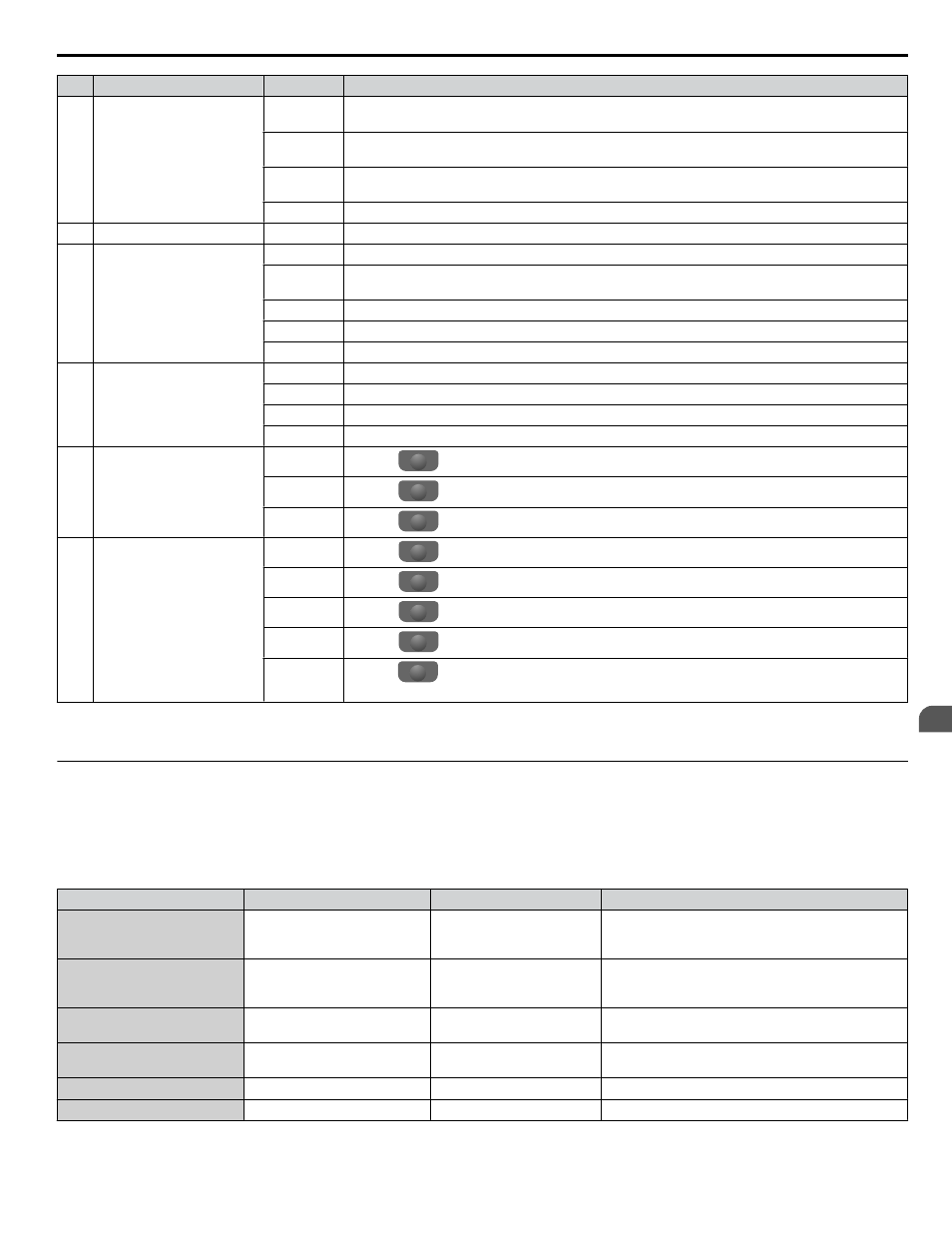
2
Bypass Status Display
AUTO
XFER EN Displayed when running in Auto Transfer, a fault was detected and switched to Bypass Mode.
ENRGY
SAVEN
Displayed when running in Energy Savings Mode
MTR
STOPPING Displayed when fault is removed but motor is still ramping down.
FAULTED Displayed when a fault has been detected causing motor output contactors to open.
3
Data Display
—
Displays specific data and operation data.
4
Frequency
Reference
Source
<1>
OPR
Displayed when the frequency reference source is the HOA keypad.
COM
Displayed when the frequency reference source is the MEMOBUS/Modbus Communication Inputs
of the drive.
OP
Displayed when the frequency reference source is an option card connected to the drive.
AI
Displayed when the function reference is assigned to an analog input.
OFF
Displayed when HAND mode is OFF.
5
HAND/OFF/AUTO
(Run or Stop) Display
<2>
RSEQ
Displayed when the Run command is supplied from a remote source in OFF or AUTO Modes.
LSEQ
Displayed when the Run command is supplied from the operator keypad in HAND Mode.
RREF
Displayed when the Run command is supplied from a remote source in OFF or AUTO Modes.
LREF
Displayed when the Run command is supplied from the operator keypad in HAND Mode.
6
Function Key 2
(F2)
DATA
Pressing
F2
scrolls to the next display.
→
Pressing
F2
scrolls the cursor to the right.
DRV/BYP Pressing
F2
toggles selection between Bypass Mode and Drive Mode.
7
Function Key 1
(F1)
HELP
Pressing
F1
displays the Help menu.
←
Pressing
F1
scrolls the cursor to the left.
HOME
Pressing
F1
returns to the top menu (Frequency Reference).
ESC
Pressing
F1
returns to the previous display.
RLY
Pressing
F1
selects/deselects Drive Test Mode. During Drive Test Mode, power is applied to the
drive while in Bypass Mode by forcing the drive input contactor to close (3-contactor bypass only).
<1> Displayed when in Frequency Reference Mode.
<2> Displayed when in Frequency Reference Mode and Monitor Mode.
u
Bypass Control Board LEDs
The bypass control board has six bi-color LEDs.
The operational states of the bypass LEDs after completion of the power-up diagnostic LED sequence are described in
Table 4.2 Bypass Control Board LED States
Name
Description
Color
Behavior
MS
Module Status
Green
Turns ON when transmitting
Turns OFF when receiving
(Internal serial communications)
NS
Network Status
Green
Turns ON when transmitting
Turns OFF when receiving
(External serial communications)
ST1
ST1, Status 1
Green
Round status
Toggles ON/OFF every 500 rounds
ST2
ST2, Status 2
Green
Scan status
Toggles ON/OFF every 500 scans
ST3
ST3, Status 3
Green
Not used
ST4
ST4, Status 4
Green
Not used
4.2 Using the HOA Keypad
YASKAWA SIEP YAIZ1D 01A Z1000U HVAC MATRIX Drive Bypass Technical Manual
113
4
Start-Up Programming & Operation