Yaskawa Z1000U HVAC Matrix Bypass User Manual
Page 352
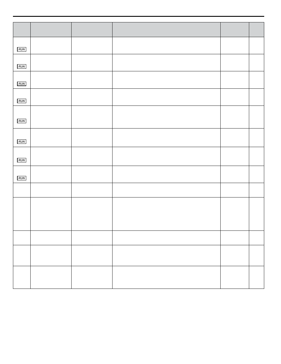
No.
(Addr.
Hex)
Name
LCD Display
Description
Values
Page
Z1-33
(85E6) Loss of Load Drive
Output Current
Load Drive Curr
The drive output current must be equal to or less than this value
to detect a loss of load.
Default: 0.0 A
Min.: 0.0
Max.: 999.9
Z1-34
(85E7) Loss of Load Drive
Time
Load Drive Time
The conditions must be met for the length of time entered here
before detecting a loss of load while in Drive mode.
Default: 1.0 s
Min.: 0.0
Max.: 300.0
Z1-35
(85E8) Loss of Load Bypass
Output Current
Load Byp Cur
The motor current must be equal to or less than this value to detect
a loss of load.
Default: 0.0 A
Min.: 0.0
Max.: 999.9
Z1-36
(85E9) Loss of Load Bypass
Time
Load Byp Time
The conditions must be met for the length of time entered to this
parameter before detecting a loss of load while in Bypass mode.
Default: 1.0 s
Min.: 0.0
Max.: 300.0
Z1-37
(85EA) Set Time
Set Time
0: Normal display
1: Time Setting
2: Reset Time
Changes the LCD display to time setting to set the Real Time
Clock.
0: Normal display
1: Displays time and date setting mode
2: Reset time
Default: 0
Range: 0 to 2
Z1-38
(85EB) HOA Source Select
HOA Select
0: Operator
1: Digital Inputs
2: Ser Comm & Opt
0: Operator
1: Digital Inputs
2: Serial Communications
Default: 0
Range: 0 to 2
Z1-39
(85EC) Drive/Bypass Source
Select
Drv/Byp Select
0: Operator
1: Digital Inputs
2: Ser Comm & Opt
0: Operator
1: Digital Inputs
2: Serial Communications
Default: 0
Range: 0 to 2
Z1-40
(85ED) Auto Transfer Wait
Time
Auto Xfer Wait T
If Auto Transfer is enabled and a drive fault is detected, the
bypass controller will wait this length of time before switching
to bypass.
Default: 0.0 s
Min.: 0.0
Max.: 300.0
Z1-41
(85EE)
Hand Speed Reference
Selection
Hand Spd Ref Sel
0: Parameter Z1-09
1: Analog
Selects the frequency reference source when in HAND Mode.
0: Parameter Z1-09
1: Analog
Default: 0
Range: 0, 1
Z1-42
(85EF) Bypass Device Type
Byp Device Type
0: Contactor
1: Soft Starter
Selects the type of device that is used for the bypass.
0: Contactor
1: Soft Starter
Note:
Setting 1 is required for bypasses with the soft-
starter option PW. This parameter is set to the
correct value at the factory. It should not require
adjustment.
Default: 0
Range: 0, 1
Z1-50
(85F7)
Bypass Unbalanced
Current Detection
Level
Byp Unbal Level
Sets the current unbalance level between phases when operating
in Bypass Mode.
Default: 25.0%
Min.: 5.0
Max.: 25.0
Z1-51
(85F8)
Bypass Unbalance Trip
Time Detection Level
Byp Unbal Time
Sets the trip time for an unbalance condition operating in Bypass
Mode.
Note:
Setting this parameter to 0.0 will disable unbalance
detection.
Default: 5.0 s
Min.: 0.0
Max.: 30.0
Z1-52
(85F9) Bypass Phase Rotation
Byp Phs Rotation
0: Disabled
1: Alarm
2: Fault
Determines the action to take when Bypass Mode phase rotation
is incorrect
0: Disabled
1: Alarm
2: Fault
Default: 1
Range: 0 to 2
<1> Values are given in Hz, but actual values are dependent upon unit settings using drive parameters o1-03, o1-09, o1-10, and o1-11.
B.15 Z: Bypass Parameters
352
YASKAWA SIEP YAIZ1D 01A Z1000U HVAC MATRIX Drive Bypass Technical Manual