H3: multi-function analog inputs – Yaskawa Z1000U HVAC Matrix Bypass User Manual
Page 174
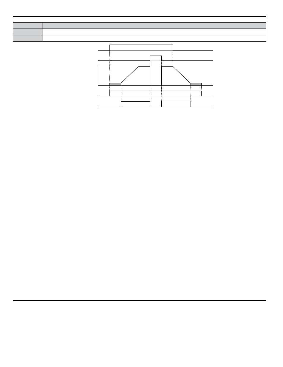
Status
Description
Open
Drive is stopped or one of the following functions is being performed: baseblock, DC Injection Braking, Short Circuit Braking.
Closed
Drive is outputting frequency.
ON
ON
OFF
OFF
ON
OFF
ON
run command
baseblock
command
output
frequency
during run
during frequency
output
OFF
Figure 5.31 During Frequency Output Time Chart
Setting 38: Drive Enable
Reflects the status of a digital input configured as a “Drive enable” input (H1-oo = 6A). If that digital input closes, then the
digital output set for “Drive enable” will also close.
Setting 39: Energy Pulse Output
Outputs a pulse to indicate the watt hours.
Setting 3A: Regen Pulse Output
Outputs a pulse to indicate the regenerated power.
Setting 3D: During Speed Search
The output terminal closes while Speed Search is being performed.
Setting 4C: During Fast Stop
The output terminal closes when a Fast Stop is being executed. .
Setting 4D: oH Pre-Alarm Time Limit
The output terminal closes when the drive is reducing the speed due to a drive overheat alarm (L8-03 = 4) and the overheat
alarm has not disappeared after 10 frequency reduction operation cycles.
Setting 60: Internal Cooling Fan Alarm
The output closes when the drive internal cooling fan has failed.
Setting 64: During Commercial Power Operation
Output closes when operating on commercial power when commercial power switching is selected (b1-24 = 1).
Setting 100 to 164: Functions 0 to 64 with Inverse Output
These settings have the same function as settings 0 to 64, but with inverse output. Set as 1oo, where the “1” indicates inverse
output and the last two digits specify the setting number of the function.
Examples:
• Set 108 for inverse output of “8: During Baseblock 1 (N.O.)”.
• Set 14D for inverse output of “4D: oH Pre-Alarm Time Limit”.
u
H3: Multi-Function Analog Inputs
The drive is equipped with multi-function analog input terminals A1, A2, and A3.
Refer to Multi-Function Analog Input
for a listing of the functions that can be set to these terminals.
n
H3-01: Terminal A1 Signal Level Selection
Selects the input signal level for analog input A1. Set jumper S1 on the terminal board accordingly for voltage input or current
input.
5.7 H: Terminal Functions
174
YASKAWA SIEP YAIZ1D 01A Z1000U HVAC MATRIX Drive Bypass Technical Manual