Bypass operations by n2, Observing the bypass operation, Controlling the bypass – Yaskawa Z1000U HVAC Matrix Bypass User Manual
Page 437: F.4 bypass operations by n2

F.4 Bypass Operations by N2
The drive operations that can be performed by N2 communication depend on drive parameter settings. This section explains
the functions that can be used and related parameter settings.
u
Observing the Bypass Operation
A controller can perform the following actions with N2 communications at any time regardless of parameter settings (except
for Z3-oo parameters):
• Observe drive status and drive control terminal status from a controller
• Read and write parameters
• Set and reset faults
• Set multi-function inputs.
Note:
Input settings from the input terminals So and from N2 communications are both linked by a logical OR operation.
u
Controlling the Bypass
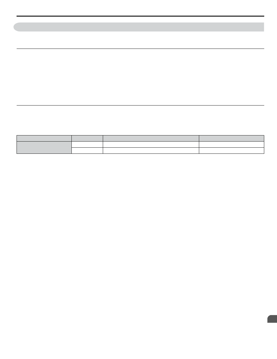
Select an external reference and adjust the parameters in
accordingly to start and stop the drive or set the frequency
reference using N2 communications.
Table F.1 Setting Parameters for Bypass Control from N2
Reference Source
Parameter
Name
Required Setting
External Reference 1
Z1-07
Frequency Reference Select
2
Z1-08
Run Command Select
2
n
Z1000U Bypass Functions
Each of the following functions must be enabled during start-up:
Start and Stop the Bypass
Set the Run Forward Command (BO 1) to run the in the forward direction. Set the Run Reverse Command (BO 2) to run the
in the reverse direction. Run/Stop Monitor (BI 1) shows the current run status. Forward/Reverse Monitor (BI 2) shows the
current direction.
NOTICE: Damage to Equipment. Improper motor direction may damage HVAC equipment if parameter b1-04, Reverse Enable, is set to 0
(Enable).
Digital Inputs
Multi-Function Input S3 (BO 5) through Multi-Function Input S7 (BO 9) are physical digital inputs on the bypass. They can
be set either by external devices, such as limit or pressure switches, or by the network. Their function depends on how the
bypass has been programmed. The multi-function input status can be monitored through Multi-Function Input 3 Monitor (BI
15) through Multi-Function Input 7 Monitor (BI 19). The Multi-Function Input # Monitor state is the logical OR of the serial
command value (BO 5 through BO 9) and the state of the external connection.
Note:
The multi-function inputs can be set by both external devices or over the network. Use caution when connecting the multi-function inputs
to external devices to ensure correct system operation.
Digital Outputs
Multi-Function Output 7 (BI 10) through Multi-Function Output 9 (BI 12) are physical digital outputs on the bypass. Their
function depends on how the bypass is programmed.
Loop Gain
PID Proportional Gain (AO 4) and PID Integral Time (AO 5) are the gain and integral time parameters used by the drive. The
drive PID loop is structured differently than the Metasys loop.
Reading and Resetting Faults
The Fault Monitor (BI 4) and Drive Ready Monitor (BI 3) show the current status of the bypass. The Fault Code (AI 10)
contains the code for the most current fault. The LST Fault Code (AI 19) contains the code for the previous drive fault.
to Fault Trace / History Register Contents on page 439
for descriptions of the fault codes. The drive faults can be reset
through the Fault Reset Command (BO 4). The Fault Reset Command is only available when the Run Forward Command and
the Run Reverse Command are both OFF.
F.4 Bypass Operations by N2
YASKAWA SIEP YAIZ1D 01A Z1000U HVAC MATRIX Drive Bypass Technical Manual
437
F
Metasys N2 Network Protocol