L8: drive protection – Yaskawa Z1000U HVAC Matrix Bypass User Manual
Page 333
No.
(Addr.
Hex)
Name
LCD Display
Description
Values
Page
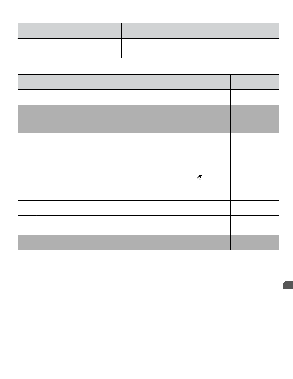
L6-14
(062F)
Motor Underload
Protection Level at
Minimum Frequency
Underload Level
Sets the UL6 detection level at minimum frequency by
percentage of drive rated current.
Default: 15%
Min.: 0
Max.: 300
u
L8: Drive Protection
No.
(Addr.
Hex)
Name
LCD Display
Description
Values
Page
L8-02
(04AE) Overheat Alarm Level OH Pre-Alarm Lvl
An overheat alarm occurs when heatsink temperature exceeds
the L8-02 level.
Default:
<1>
Min.: 50 °C
Max.: 150 °C
L8-03
(04AF)
Overheat Pre-Alarm
Operation Selection
OH Pre-Alarm Sel
0: Ramp to stop
1: Coast to stop
2: Fast-Stop
3: Alarm only
4: Run@L8-19 Rate
0: Ramp to stop. A fault is triggered.
1: Coast to stop. A fault is triggered.
2: Fast Stop. Decelerate to stop using the deceleration time in
C1-09. A fault is triggered.
3: Continue operation. An alarm is triggered.
4: Continue operation at reduced speed as set in L8-19.
Default: 4
Range: 0 to 4
–
L8-05
(04B1)
Input Phase Loss
Protection Selection
Inp Ph Loss Det
0: Disabled
1: Enabled
Selects the detection of input current phase loss, power supply
voltage imbalance, or main circuit electrolytic capacitor
deterioration.
0: Disabled
1: Enabled
Default: 1
Range: 0, 1
L8-06
(04B2)
Input Phase Detection
Level
Inp Ph Loss Lvl
When ripple is observed in the DC bus, expansion of the input
bias is calculated. This value becomes the input phase if the
difference between the maximum and minimum values of the
ripple is greater than the value set to L8-06.
Detection Level = 100% = Voltage class x
Default:
<1>
Min.: 0.0%
Max.: 50.0%
L8-07
(04B3)
Output Phase Loss
Protection Selection
Outp Ph Loss Det
0: Disabled
1: 1PH Loss Det
2: 2/3PH Loss Det
0: Disabled
1: Enabled (triggered by a single phase loss)
2: Enabled (triggered when two phases are lost)
Default: 1
Range: 0 to 2
L8-09
(04B5)
Output Ground Fault
Detection Selection
Grnd Flt Det Sel
0: Disabled
1: Enabled
0: Disabled
1: Enabled
Default:
<1>
Range: 0, 1
L8-38
(04EF)
Carrier Frequency
Reduction
Fc Reduct dur OL
0: Disabled
1: Active below 6Hz
2: Active @ any Spd
0: Disabled
1: Enabled below 6 Hz
2: Enabled for the entire speed range
Default:
<1>
Range: 0 to 2
L8-40
(04F1)
Carrier Frequency
Reduction Off Delay
Time
Fc Reduct Time
Sets the time that the drive continues running with reduced
carrier frequency after the carrier reduction condition is gone.
Setting 0.00 s disables the carrier frequency reduction time.
Default: 0.50 s
Min.: 0.00
Max.: 2.00
–
<1> Default setting is dependent on parameter o2-04, Drive Model Selection.
B.9 L: Protection Function
YASKAWA SIEP YAIZ1D 01A Z1000U HVAC MATRIX Drive Bypass Technical Manual
333
B
Parameter List