Figure 1.6 – Yaskawa Z1000U HVAC Matrix Bypass User Manual
Page 64
B
G
E
F
M
A
D
A
B
C
D
C
C
G
C
L
H
I
J
K
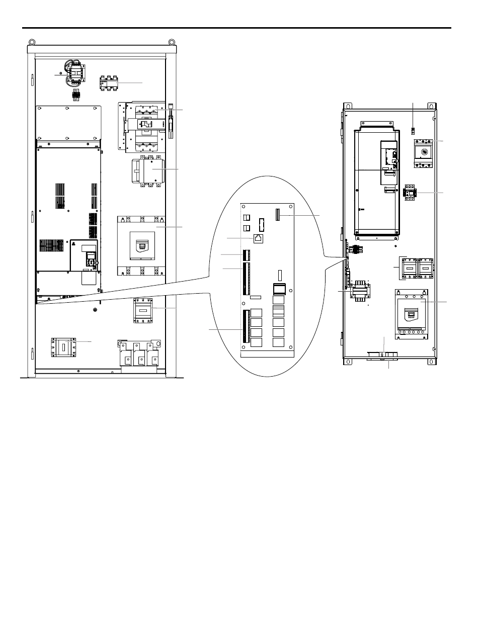
A – Main input disconnect
B – Motor overload
C – Bypass contactor
D – Soft starter option PW
E – Air filter
F – Enclosure cooling fan
G – 120 V control transformer
H – Terminal TB1
I – Terminal TB2
J – Terminal TB3
K – Communications port CN2
L – Option card connector CN5
M – Ground terminal
Figure 1.6 Interior View of Bypass Unit
n
Circuit Breaker (100 kAIC)
Electrically located on the input power side of the bypass, the door mounted circuit breaker provides a means of disconnecting
the bypass from line power for equipment maintenance. The circuit breaker must be in the OFF position to open the bypass
enclosure door. When opened, the handle can be locked in the OFF position using a padlock.
Branch short circuit protection for the bypass must be supplied by the customer.
n
Contactors
The bypass is a 2-contactor or 3-contactor bypass circuit employing IEC rated contactors in an electrically interlocked
arrangement to allow mutually exclusive operation in Drive or Bypass modes.
The control logic and “soft start” characteristic of the drive limit the drive input and output contactors to motor FLA current
or less. For this reason, the drive output contactor has a lower current rating than the bypass contactor. The bypass contactor
is exposed to motor inrush current (LRA) when starting the motor across-the-line and therefore requires a higher current rating.
1.5 Bypass Component Descriptions
64
YASKAWA SIEP YAIZ1D 01A Z1000U HVAC MATRIX Drive Bypass Technical Manual