Bypass and drive control i/o connections, Terminals a1, a2, and a3 input signal selection, Terminal am/fm signal selection – Yaskawa Z1000U HVAC Matrix Bypass User Manual
Page 105: 6 bypass and drive control i/o connections, Shows the location of these switches, For setting
3.6 Bypass and Drive Control I/O Connections
u
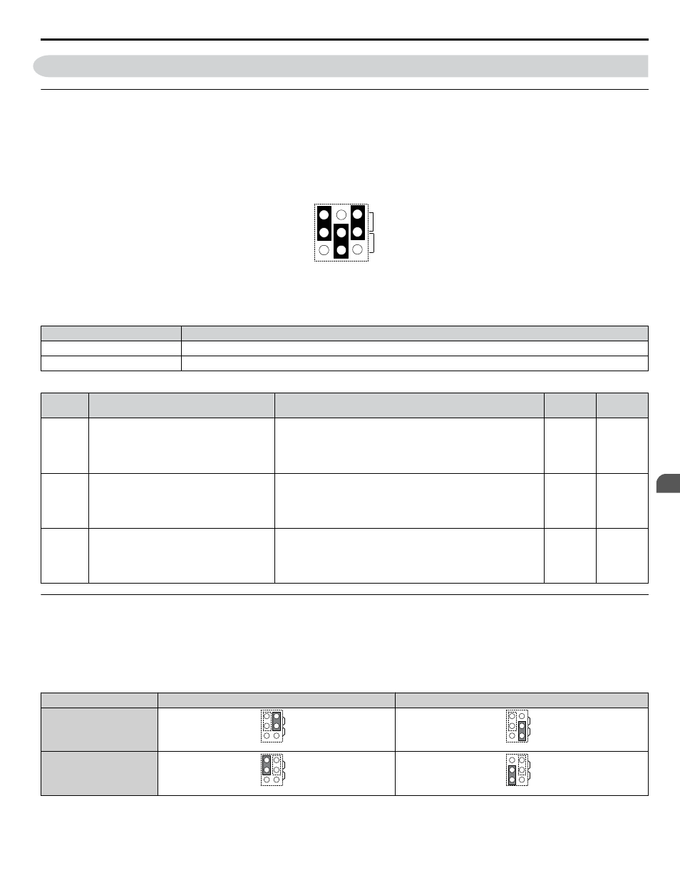
Terminals A1, A2, and A3 Input Signal Selection
Terminals A1, A2, and A3 can be used to input either a voltage or a current signal. Select the signal type using jumper S1 as
. Set parameters H3-01, H3-05, and H3-09 accordingly as shown in
.
and Jumpers on the Terminal Board on page 104
for locating jumper S1.
Note:
If terminals A1 and A2 are both set for frequency bias (H3-02 = 0 and H3-10 = 0), both input values will be combined to create the frequency
reference.
V
I
A1 A2 A3
Jumper S1
Figure 3.35 Terminal A2 Set to Current Input; A1 and A3 Set to Voltage Input
Table 3.12 Jumper S1 Settings
Setting
Description
V (top position)
Voltage input (-10 to +10 V or 0 to 10 V)
I (bottom position)
Current input (4 to 20 mA or 0 to 20 mA)
Table 3.13 Voltage/Current Selection Parameter Details
No.
Parameter Name
Description
Setting
Range
Default
Setting
H3-01
Terminal A1 signal level selection
Selects the signal level for terminal A1.
0: 0 to 10 Vdc
1: 0 to 10 Vdc Bipolar
2: 4 to 20 mA
3: 0 to 20 mA
0 to 3
0
H3-05
Terminal A3 signal level selection
Selects the signal level for terminal A3.
0: 0 to 10 Vdc
1: 0 to 10 Vdc Bipolar
2: 4 to 20 mA
3: 0 to 20 mA
0 to 3
0
H3-09
Terminal A2 signal level selection
Selects the signal level for terminal A2.
0: 0 to 10 Vdc
1: 0 to 10 Vdc Bipolar
2: 4 to 20 mA
3: 0 to 20 mA
0 to 3
2
u
Terminal AM/FM Signal Selection
The signal type for terminals AM and FM can be set to either voltage or current output using jumper S5 on the terminal board
as explained in
. When changing the setting of jumper S5, parameters H4-07 and H4-08 must be set accordingly.
The default selection is voltage output for both terminals.
Refer to Switches and Jumpers on the Terminal Board on page
for locating jumper S5.
Table 3.14 Jumper S5 Settings
Terminal
Voltage Output
Current Output
Terminal AM
AM
FM
V
I
AM
FM
V
I
Terminal FM
AM
FM
V
I
AM
FM
V
I
3.6 Bypass and Drive Control I/O Connections
YASKAWA SIEP YAIZ1D 01A Z1000U HVAC MATRIX Drive Bypass Technical Manual
105
3
Electrical Installation