Simplified setup using the quick setting group, Quick setting parameters – Yaskawa Z1000U HVAC Matrix Bypass User Manual
Page 120
u
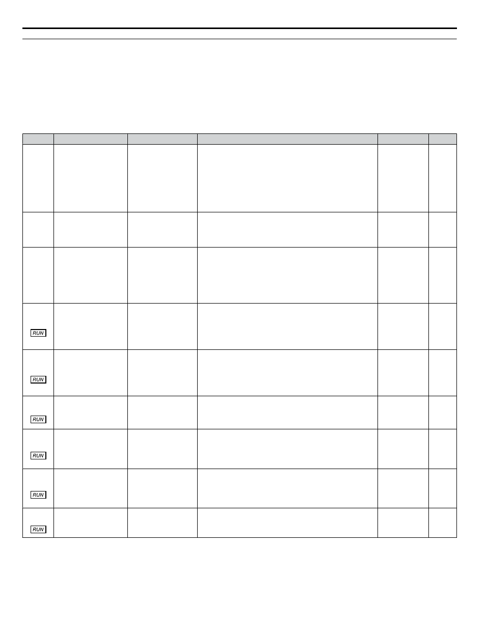
Simplified Setup Using the Quick Setting Group
The Quick Setting Group lists only the basic parameters necessary to set up the bypass. This group expedites the startup process
by showing only the most important bypass parameters.
n
Quick Setting Parameters
lists the parameters in the Quick Setting Group.
Use the Programming Mode to access parameters not displayed in the Quick Setting Group.
Table 4.5 Quick Setting Group Parameters
No.
Name
LCD Display
Description
Values
Page
A1-06
(0127)
Application Preset
Application Sel
0: General
1: Fan General
2: Fan PID
3: Fan ReturnAir/PID
4: Cooling Tower
5: CoolingTower/PID
6: Pump Secondary
7: Pump PID
0: Standard
1: Fan
2: Fan with PID Control
3: Return Fan with PID Control
4: Cooling Tower Fan
5: Cooling Tower Fan with PID Control
6: Pump (Secondary)
7: Pump with PID Control
Default: 0
Range: 0 to 7
E1-05
(0304)
Maximum Voltage
Max Voltage
These parameters are only applicable when E1-03 is set to F.
Default:
<1>
Min.: 0.0 V
Max.: 255.0 V
<2>
E2-01
(030E) Motor Rated Current
Motor Rated FLA
Sets the motor nameplate full load current in amps.
Automatically set during Auto-Tuning.
Default:
<1>
Min.: 10% of
drive rated
current
Max.: 150% of
drive rated
current
<3>
Z1-07
(85CC) Speed Reference Select
Spd Ref Sel
0: Operator
1: Analog Input
2: Bypass Serial
3: Option Board
Determines the source of the Frequency Reference sent from
the Bypass Controller to the Drive.
0: Operator
1: Analog Input
2: Bypass Serial
3: Option Board (CN5)
Default: 1
Range: 0 to 3
Z1-08
(85CD) Run Command Select
Run Cmd Sel
0: Operator
1: Bypass DI
2: Bypass Serial
3: Option Board
Determines the source of the Auto Mode Run command used
by the Bypass Controller.
0: Operator
1: Bypass Controller Digital Input
2: Bypass Serial
3: Option Board (CN5)
Default: 1
Range: 0 to 3
Z1-09
(85CE) HAND Mode Drive
Speed Reference
Hand Fref
This is the speed reference used when the Drive is running in
HAND mode. Units are in Hz.
Default: 10.0
Hz
<4>
Min.: 0.0
Max.: 60.0
Z1-37
(85EA) Set Time
Set Time
0: Normal display
1: Time Setting
2: Reset Time
Changes the LCD display to time setting to set the Real Time
Clock.
0: Normal display
1: Displays time and date setting mode
2: Reset time
Default: 0
Range: 0 to 2
Z3-01
(8500)
Serial Communications
Protocol Select
Serial Protocol
0: Modbus
1: N2
2: P1
3: BACnet
Selects the bypass serial communications protocol.
0: Modbus
1: N2
2: P1
3: BACnet
Default: 3
Range: 0 to 3
Z3-02
(8501)
Serial Communications
Node Address Select
Node Address
Selects the bypass serial communications node address.
Default: 1
Min.: 0
Max.: 127
4.3 The Drive and Programming Modes
120
YASKAWA SIEP YAIZ1D 01A Z1000U HVAC MATRIX Drive Bypass Technical Manual