5 creating the body of the function, 6 creating the program that calls the function – Yaskawa MP920 User's Manual Design User Manual
Page 101
3.5 Functions
3-27
3
3.5.5
Creating the Body of the Function
The body of the function is created in the same way as the drawings except that the types of
register used are different. For details on the registers, see 3.6.3 Types of Register.
3.5.6
Creating the Program that Calls the Function
The user function is completed when the graphic representation and body program of the
function have been created. As with the standard system functions, user functions can be
called from any parent, child, or grandchild drawing or any other user function.
Functions can be called from a drawing or from within the program of another user function
by using the following procedure. For details on the operation methods, refer to the Machine
Controller MP900/MP2000 Series User’s Manual: Ladder Programming (SIEZ-C887-1.2).
1. Input the function name using the FSTART instruction.
Example: Input “FSTART, Enter Key, TEST, Enter Key”.
The previously defined graphic representation of the function will be displayed.
2. Use the FIN instruction to create the input data program.
Provide input data for the function inputs and address inputs.
3. Use the FOUT instruction to create the output data program.
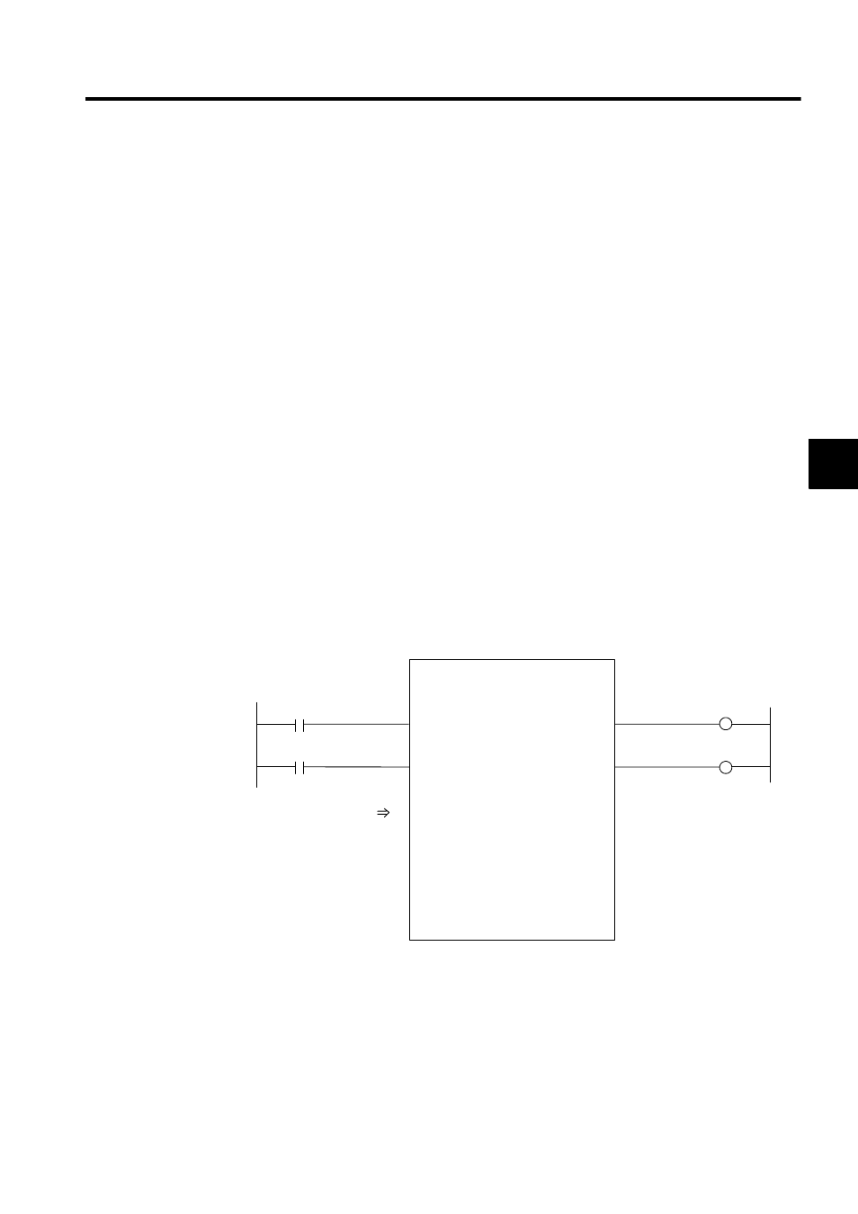
Example: I/O data is provided for the graphic representation as shown in the following
illustration.
Fig. 3.9 Graphic Representation for which Input Data is Provided (Example)
===>
===>
===>
TEST
BIT1
BIT2
FLT1
INT1
INT2
LNG1
BIT4
BIT3
ADR
MA00300
DF00001
DW00003
DB000000
DB000001
DB000020
DB000021
DL00010
DW00012