Dip switch – Yaskawa MP920 User's Manual Design User Manual
Page 205
5 Modules
5.2.1 CPU-01 Module
5-10
DIP Switch
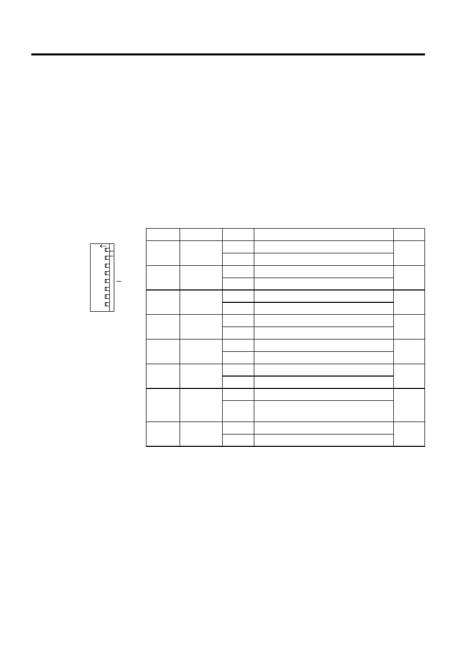
The DIP switch consists of eight pins. The pins are numbered 1 to 8, as shown in the dia-
gram with Table 5.2.
Each pin is ON when it is moved to the left.
The pins other than L.RST and M.RST are valid only when the power turns ON and at the
startup after resetting.
Turn OFF the power and then ON again when changing the mode.
The function of each pin is described below.
Table 5.2 DIP Switch Functions
Pin
Name
Setting
Function
Default
1
L. RESET
ON
Local reset
OFF
OFF
Online
2
RUN
ON
User program executed.
ON
OFF
User program stopped.
3
INITIAL
ON
Pin 4 ON: Memory cleared.
OFF
OFF
Pin 4 ON: Setting disabled.
4
TEST
ON
Terminal mode/initialization mode
OFF
OFF
Online
5
PP
Defaults
ON
Defaults for port 1 only
OFF
OFF
Use memory settings.
6
MULTI
ON
Multiple CPU in configuration
OFF
OFF
Single CPU in configuration
7
FLASH
ON
Program copied from flash memory to RAM.
OFF
OFF
Program not copied from flash memory to
RAM.
8
M.RST
ON
Master reset
OFF
OFF
Online
SW1
L.RST
RUN
INIT
TEST
MULTI
FLASH
M.RST
ON
OFF
ON
123
456
7
8