Yaskawa MP920 User's Manual Design User Manual
Page 271
5 Modules
5.5.1 Servo Module (4-axis)
5-76
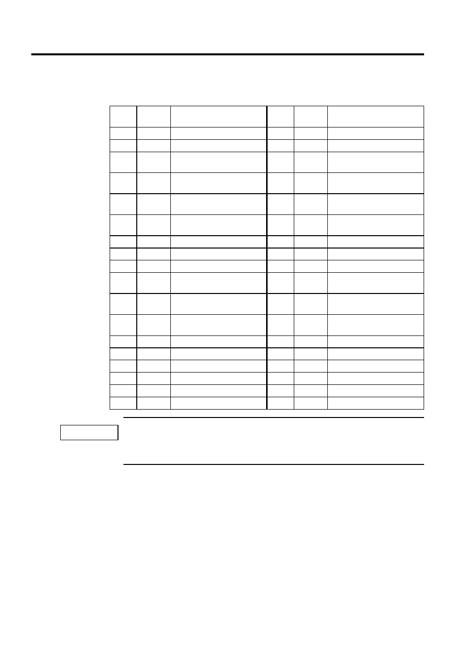
The following table shows the name and function of the pins of the CN1 to CN4 connectors.
Either 5 V or 24 V can be selected for the SEN signal. Connect the SEN signal to either Pin 20 or Pin
32 according to the application.
The standard cable is connected to Pin 20.
Pin
No.
Signal
Name
Function
Pin
No.
Signal
Name
Function
1
SG
Ground (for analog)
19
SG
Ground (for SEN signal)
2
NREF
Speed reference
20
SEN
SEN signal
3
PA
5-V differential pulse input (+)
21
0BAT
BAT output terminal (-) for
absolute specification
4
PAL
5-V differential pulse input (-)
22
BAT
BAT output terminal (+) for
absolute specification
5
PC (5V)
5-V differential pulse input (+)
23
PB
5-V differential B pulse termi-
nal (+)
6
PCL
(5V)
5-V differential pulse input (-)
24
PBL
5-V differential B pulse termi-
nal (-)
7
SG
Ground
25
SG
Ground
8
26
9
27
10
0V
(24V)
0 V (24 V)
28
0V
(24V)
0 V (24 V)
11
0V
(24V)
0 V (24 V)
29
0V
(24V)
0 V (24 V)
12
PCON
P operation reference, DO-2
30
ALM
RST
Alarm reset, DO-1
13
OTR
Overtravel (-)
31
SV ON
Servo ON, DO-0
14
OTF
Overtravel (+)
32
SEN
VS866 SEN output
15
33
16
+24V
+24 V power supply
34
+24V
+24 V power supply
17
SV ALM Servo alarm input, DI-0
35
SRDY
Servo ready input, DI-1
18
BRK
Brake ON input, DI-2
36
IMPORTANT