2 start and stop sequences, 1 dip switch settings – Yaskawa MP920 User's Manual Design User Manual
Page 78
3 Basic System Operation
3.2.1 DIP Switch Settings
3-4
3.2
Start and Stop Sequences
This section explains the start and stop sequences of the MP920. The methods of setting the DIP
switch, the types of self-diagnosis, and the indicator patterns are also explained.
3.2.1
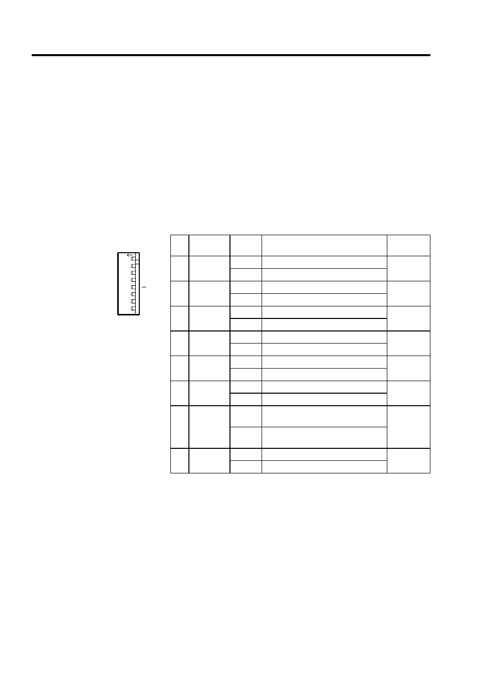
DIP Switch Settings
The DIP switch on the CPU Module are used to control start and stop sequences. As shown
in the figure below, there are eight pins on the DIP switch on the CPU Module. Table 3.1
shows the function of each pin.
Table 3.1 DIP Switch Pin Functions
Pin
Name
Setting
Function
Default
Setting
1
L.RST
ON
Local reset
OFF
OFF
Online
2
RUN
ON
User program operating
ON
OFF
User program stopped
3
INITIAL
ON
Pin 4 ON: Memory clear
OFF
OFF
Pin 4 ON: Setting disabled
4
TEST
ON
Terminal mode/initialization mode
OFF
OFF
Online
5
PP Default
ON
Defaults for port 1 only
OFF
OFF
Use memory settings
6
MULTI
ON
Multiple CPU configuration
OFF
OFF
Single CPU configuration
7
FLASH
ON
Copy program data from flash memory
to RAM
OFF
OFF
Do not copy program data from flash
memory to RAM
8
M.RST
ON
Master reset
OFF
OFF
Online
SW1
L.RST
RUN
INIT
TEST
MULTI
FLASH
M.RST
ON
OFF
ON
12
3
456
7
8