Cable connection diagram – Yaskawa MP920 User's Manual Design User Manual
Page 295
5 Modules
5.5.3 MECHATROLINK Interface Module (SVB-01)
5-100
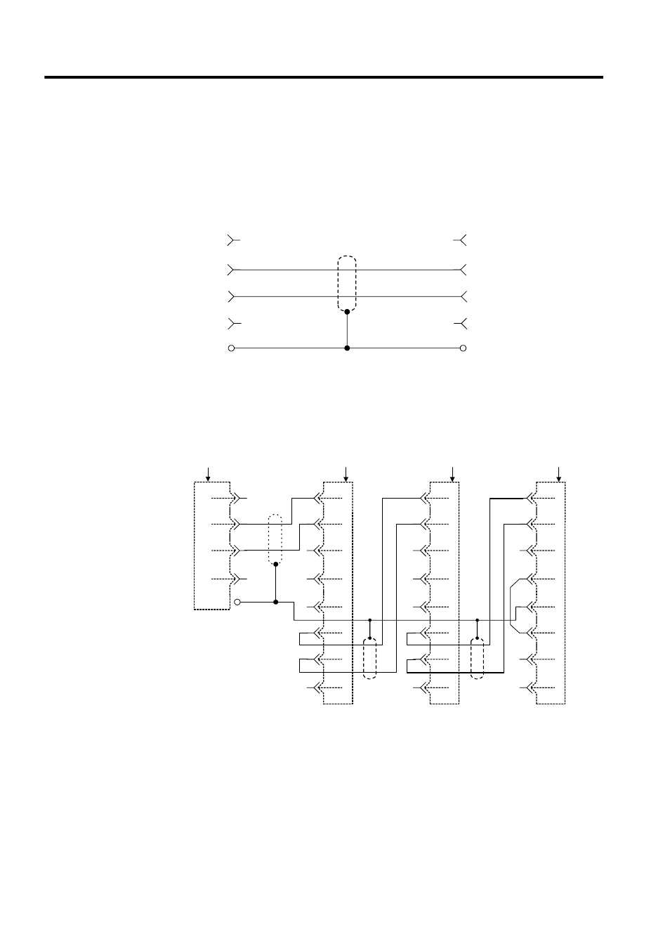
Cable Connection Diagram
The following figure shows the cable internal connection between the SVB-01 Module and
the IO350 I/O unit.
The connections when one SVB-01 Module is connected to multiple SERVOPACKs (1: N
transmission) using MECHATROLINK cables is shown below.
Note: 1. The JEPMC-6010- cable has a USB connector on one end and
loose wires on the other end. The customer must assemble the
cable for 1: N connection using the appropriate MR connectors and
wires.
2. Red lead: DATA
Black lead: /DATA
3. The shield can be connected according to the instructions given in
the corresponding SERVOPACK manual. However, the connec-
tion shown above is recommended when connecting MP900-series
Machine Controllers.
Cable Model: JEPMC-W6000-A3
Name
Pin No.
Name
Pin No.
Shell
Shell
Shield
Shield
1
2
3
4
(NC)
/DATA
DATA
SH
1
2
3
4
(NC)
/DATA
DATA
SH
FG
1
2
3
4
/DATA
(NC)
DATA
SH
TERM
/DATA
1
2
3
4
DATA
/DATA
DATA
5
6
7
8
TERM
/DATA
1
2
3
4
DATA
/DATA
DATA
5
6
7
8
TERM
/DATA
1
2
3
4
DATA
/DATA
DATA
5
6
7
8
Cable Model: JEPMC-W6010-
I/O unit
USB connector
Shield
Shell
SERVOPACK
MR connector
SERVOPACK
MR connector
SERVOPACK
(terminator)
MR connector