Led indicator 2, Mechatrolink connector connector specifications, Cn1 connections – Yaskawa MP920 User's Manual Design User Manual
Page 294
5.5 Motion Modules
5-99
5
LED Indicator 2
The TRX indicator displays the communications status of the SVB-01 Module.
MECHATROLINK Connector
Connector Specifications
The following table shows the specifications of the connector used to connect the SVB-01
Module.
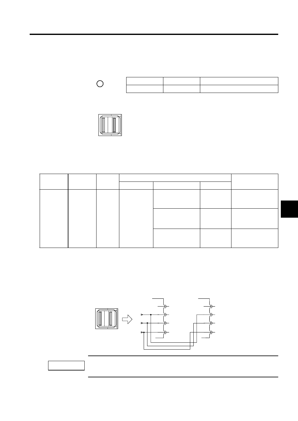
CN1 Connections
The connector ports on the right and left sides of the CN1 are the same. Use either the left or
rigth port.
Insert an USB terminator JEPMC-W6020 in the unused port.
The SVB-01 Module has MECHATROLINK port for one channel. Two ports are provided on the CN1
MECHATROLINK connector, however, these two ports are the same as shown in the figure above.
Indicator Name
Indicator Color
Meaning When Indicator Is Lit
TRX
Green
Transmission enabled
The MECHATROLINK connector is used to connect an SVB-01 Mod-
ule and SERVOPACK and IO350 unit using MECHATROLINK cables
(JEPMC-W6000-A3 or JEPMC-W6000-01).
TRX
Name
Connector
Name
Number
of Pins
Connector
Cable
On Module
On Cable
Manufacturer
MECHATR-
OLINK
Connector
CN1
4
DUSB-APA42-
T11
USB-USB
connector boby:
DUSB-APA41-B1-C50
DDK
JEPMC-W6000-A3
USB-Loose wires
connector boby:
DUSB-APA41-B1-C50
DDK
JEPMC-W6010-01
JEPMC-W6010-03
JEPMC-W6010-05
USB terminator
connector boby:
DUSB-APA41-B1-C50
DDK
JEPMC-W6020
Left side on CN1
Right side on CN1
CN1
1
2
3
4
1
2
3
4
NC
SH
DATA
/DATA
NC
SH
DATA
/DATA
IMPORTANT