2 setting up a multi-cpu system, 1 hardware settings – Yaskawa MP920 User's Manual Design User Manual
Page 435
9 Multi-CPU System
9.2.1 Hardware Settings
9-8
9.2
Setting Up a Multi-CPU System
This section describes the settings unique to a Multi-CPU System. For settings that are the same
as a Single-CPU System, refer to 3.2 Start and Stop Sequences and Chapter5 Modules.
9.2.1
Hardware Settings
Mount one CPU Module in slots 0 and 1 and another CPU Module in slots 2 and 3 on the
Mounting Base (rack 1 in a multiple rack configuration). The CPU Module in slots 0 and 1 is
CPU Module 1, and the CPU Module in slots 2 and 3 is CPU Module 2.
CPU Module 1 and CPU Module 2 have their own CPU numbers as shown in the following
table.
Use the same model of CPU Module. Their software versions must also be the same. If the
models of the two CPU Modules are different, data sharing may not be dependable.
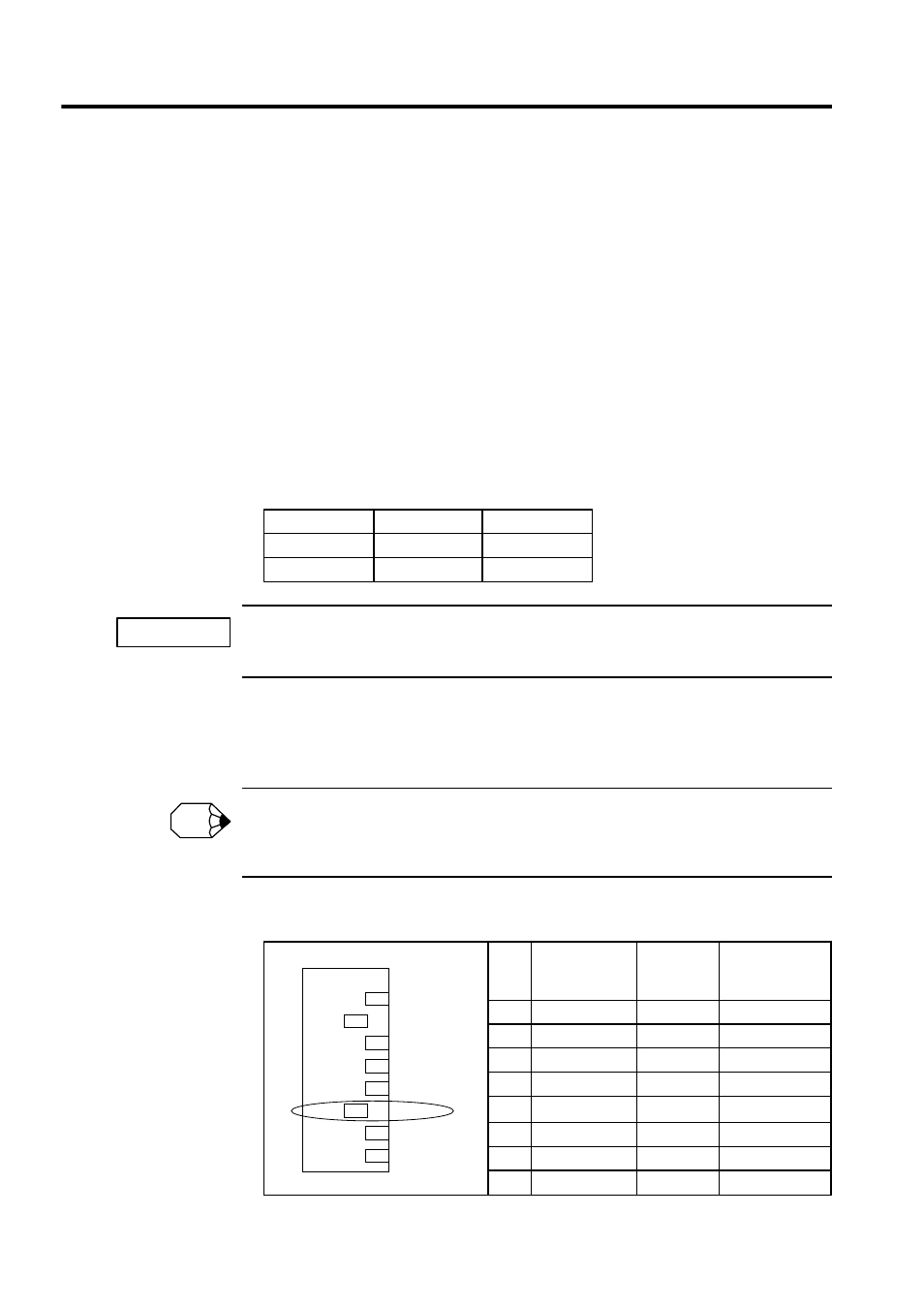
Turn ON the DIP switch pin SW1-6 (MULTI) on both CPU Module 1 and CPU Module 2.
The settings of other pins are the same as for a Single-CPU System. Refer to 3.2 Start and
Stop Sequences for details.
If SW1-6 (MULTI) on either CPU Module 1 or CPU Module 2 is OFF, the Multi-CPU System will not
operate normally. Even if the LED indicator status is correct, it will be impossible to log on from the
MPE720.
Table 9.2 Mounting Slots
Name
Mounting Slots
CPU Number
CPU Module 1
0 and 1
01
CPU Module 2
2 and 3
02
Table 9.3 DIP Switch SW1 Settings
Pin
No.
Name
Factory
Setting
Setting for
Multi-CPU
System
1
L.RESET
OFF
OFF
2
RUN
ON
ON
3
INITIAL
OFF
OFF
4
TEST
OFF
OFF
5
PP Default
OFF
OFF
6
MULTI
OFF
ON
7
FLASH
OFF
OFF
8
M.RST
OFF
OFF
IMPORTANT
INFO
1 2 3 4 5 6 7 8
ON
SW1
L.RESET
RUN
INITIAL
TEST
PP default
MULTI
FLASH
M.RST
ON OFF