Servo number led display – Yaskawa MP920 User's Manual Design User Manual
Page 513
12.3 Motion Errors
12-23
12
12.3.3
Processing Performed When an SVA Module Error Occurs
Servo Number LED Display
The status LED indicators display a servo number (1 to b) when the SVA Module is nor-
mally operating in online mode.
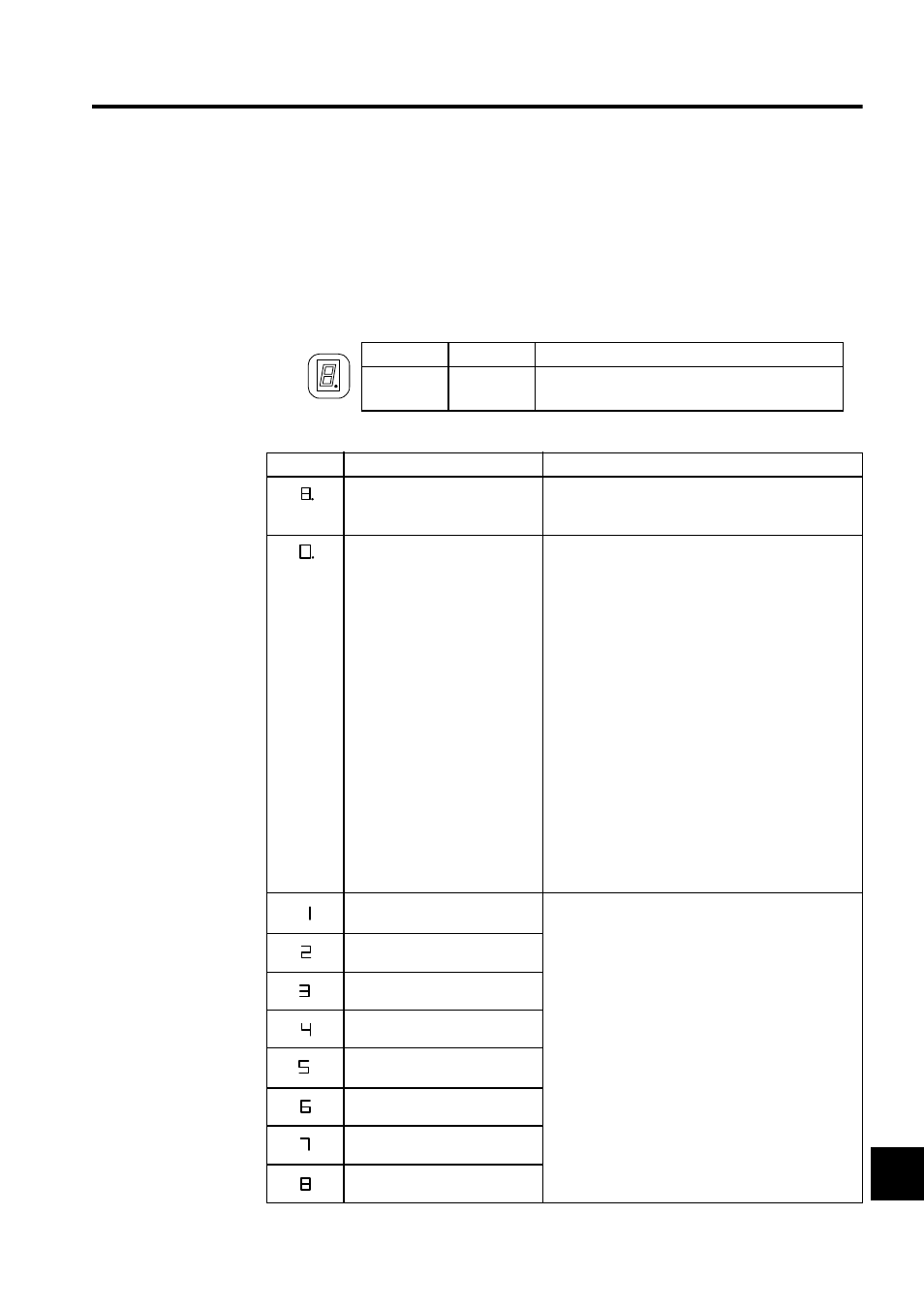
Table 12.11 LED1 (8-segment LED)
Indicator
Color
When Lit
STATUS
Green
Displays a servo number or an error.
Table 12.12 Indicator Display Status
Display
Meaning
Remedy
Hardware reset status
The hardware has been reset. Check the DIP switch
settings, and correct them as necessary. If the status
does not change, replace the Module.
Initializing
1. The system usually enters this status for one to six
seconds after the system is turned ON or reset. If
the Servo Module is set up so that an Absolute
Encoder is connected, and the interface with the
Absolute Encoder causes an error, this status will
last for 30 seconds per axis.
2. This status lasts if the system enters a permanent
loop in an A Drawing of PLC (CPU1/CPU2).
3. This display indicates that the SVA Module is not
registered in the Module definitions. To use the
Module, register it in the Module definitions and
then specify the fixed SVA parameters and the
servo parameters for each axis.
4. If 1 to 3 above do not apply, replace the Module.
5. If the problem persists, a hardware error (such as a
synchronization error during initialization for the
link between the PLC (CPU1/CPU2) and the SVA
Module) may be the cause of the problem. Replace
other Modules and racks one at a time to isolate the
problem cause.
Servo number. No. 1
A servo number (1 to 16) is displayed when the servo
is operating normally without an error or alarm. Note,
however, that this indicator display also appears when
“no axis” is selected.
Servo number. No. 2
Servo number. No. 3
Servo number. No. 4
Servo number. No. 5
Servo number. No. 6
Servo number. No. 7
Servo number. No. 8