Yaskawa MP920 User's Manual Design User Manual
Page 548
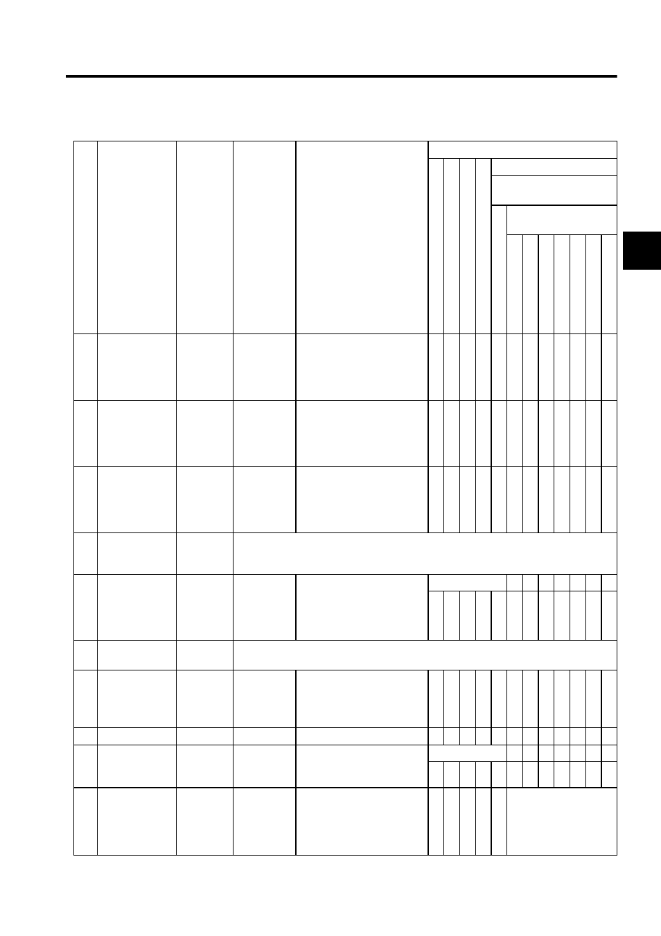
A.3 Parameter List
A-33
A
17
Cumulative
Rotations from
Absolute
Encoder
(ABSREV)
IL10
0 to
±99999
1 = 1 turn
√ √ √ √ √ √ √ √ √ √ √ √
19
Initial Incremen-
tal Pulses from
Absolute
Encoder
(IPULSE)
IL12
-2
31
to 2
31
-1
1 = 1 pulse
√ √ √ √ √ √ √ √ √ √ √ √
21
Motion Com-
mand Response
Code
(MCM-
DRCODE)
IW14
0 to 65535
Motion command that is cur-
rently executing. (See
OW20 for more details.)
√ √ √ √ √ √ √
22
Motion Com-
mand Status
(MCMDSTS)
IW15
Reports the execution status of motion command (OW20).
23
Number of Dig-
its Below Deci-
mal Point
Monitor
(DECNUMM)
IW16
0 to 5
Copies fixed motion parame-
ter Number of Digits Below
Decimal Point.
√ √ √ √ √ √ √
√ √ √ √ √
24
Position Control
Status (POSSTS)
IW17
Reports position information managed by the SVA Module.
25
Machine Coordi-
nate System Ref-
erence Position
(MPOS)
IL18
-2
31
to 2
31
-1
1 = 1 pulse for pulses
Note:Will not be updated
if the machine is
locked.
√ √ √ √ √ √ √
27
Not used
IL1A
−
−
29
POSMAX
Monitor
(PMAXMON)
IL1C
1 to 2
31
-1
1 = 1 reference unit
Copies fixed motion parame-
ter
“
POSMAX.
”
√ √ √ √ √ √ √
√ √ √ √ √
31
Number of
POSMAX
Turns
(PMAXTURN)
IL1E
-2
31
to 2
31
-1
1 = 1 turn
Counit is incremented or dece-
mented each time POSMAX is
exceeded.
(Initializes to 0 at power ON.)
Valid when infinite
length axis is selected at
fixed motion parameter
Motion Controller Func-
tion Selection Flag.
(cont’d)
No.
Name
Register
Number
Setting
Range
Meaning
Control Mode Where Data Is Valid
Zero Point Return Mode
S
pee
d Control Mode
To
rq
ue Control
Mod
e
Pha
se C
ontrol
Mode
Position Control Mode
Motion Command
Code (OB008)
Motion
C
omma
nd
Disab
led
Motion Command
Code (OW20)
Positioning
External
Posi
tion
Zero Poin
t Return
Interpol
ation
La
tch
F
eed
St
ep