Local input module connector wiring, Info – Yaskawa MP920 User's Manual Design User Manual
Page 338
6 System Startup
6.2.2 Connecting Devices
6-8
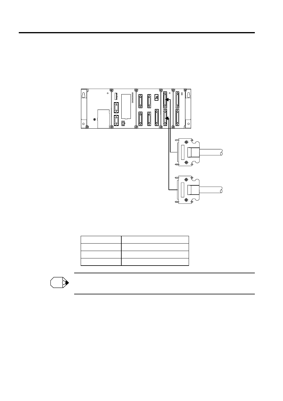
Local Input Module Connector Wiring
The following illustration shows the method of connecting the external input signal termi-
nals and the DI-01 Input Module connectors.
When connecting the external input signal terminals and the DI-01 Input Module connector,
use the following cables.
See 5.3.1 DI-01 Input Module for the DI-01 Input Module connector specifications, connector pin lay-
out, and connection examples.
External Input Cables
Cable Length
Model
0.5 m
JEPMC-W6060-05
1 m
JEPMC-W6060-10
3 m
JEPMC-W6060-30
SW1
L.RST
RUN
INIT
TEST
MULTI
FLASH
M.RST
ON
OFF
ON
1
2
3
4
5
6
7
8
PORT2
PORT1
CN1
RLY OUT
BATTERY
RDY
PRT1
RUN
ALM
ERR
BAT
ALM
PRT2
MP920 CPU-01
SVA-01
CN1
CN3
CN2
CN4
STATUS
CN5
DI-01
CN1
CN2
RUN
DO-01
CN1
CN2
RUN
FUSE
PS-03
DC24V
POWER
TB1
+24V
0V
FG
SG
To external
input signal
terminals
To external
input signal
terminals
PS-03
CPU-01
SVA-01A
DI-01 DO-01
To CN1 connector
To CN2 connector
INFO