Ladder logic program example – Yaskawa MP920 User's Manual Design User Manual
Page 132
4 Motion Control
4.2.4 Phase Control Mode
4-18
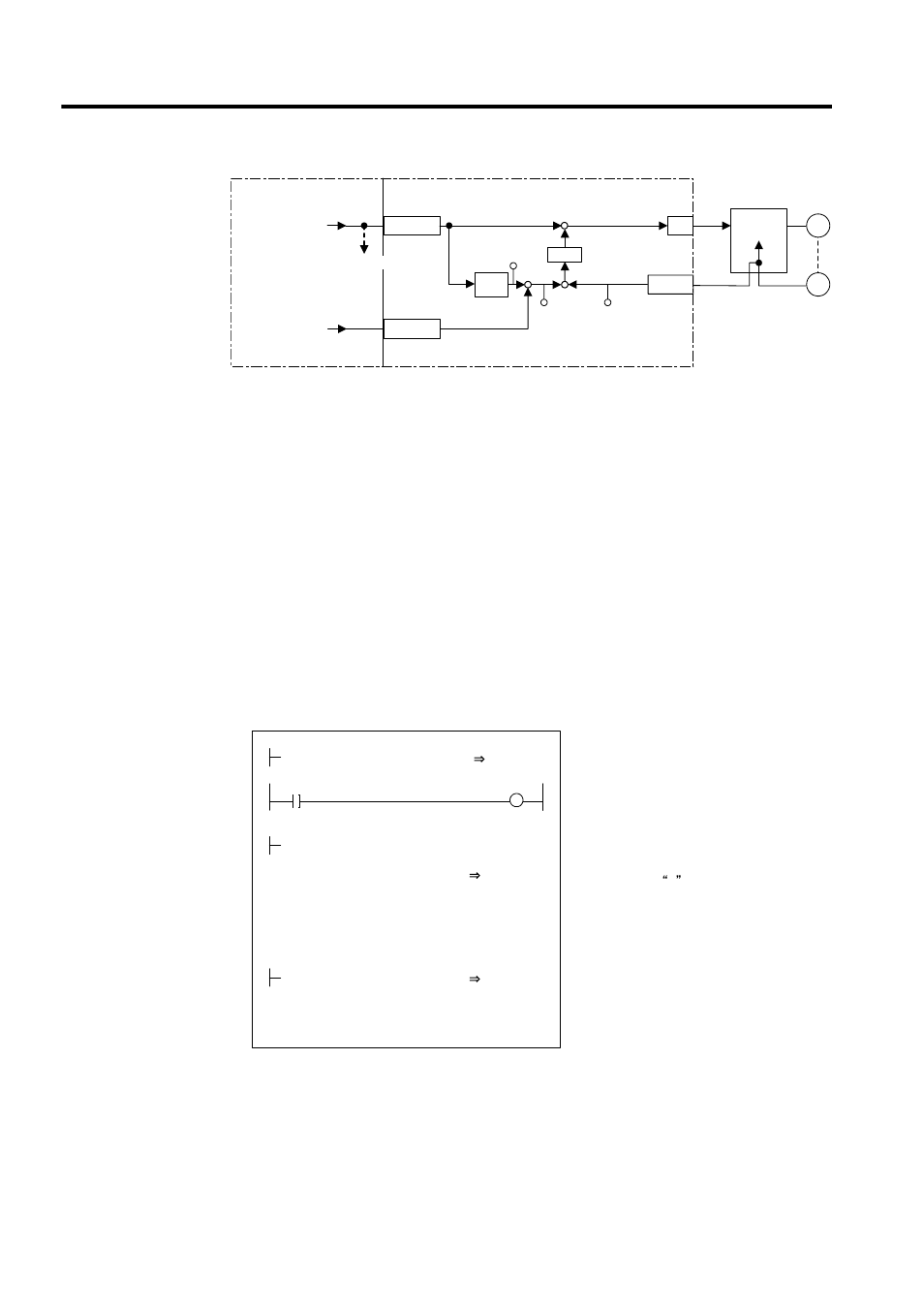
* 1. Integrates the reference speed reference, and calculates the correspond-
ing position (pulse).
* 2. Generates the speed reference from the target position (CPOS) and cur-
rent position (APOS) error
ε. This is the position (phase) compensa-
tion.
* 3. To move the phase, the distance to be moved (the angle of rotation of
the motor axis converted to the number of pulses) can be added as the
phase compensation setting.
Fig. 4.6 Block Diagram of Phase Control Loop
The rotational phase of the motor can be managed (controlled) using the above method.
This control loop is processed in the SVA-02A Module. Therefore, the user can easily control
the electronic shaft simply by selecting the phase control mode on the CPU Module and pro-
viding the required parameters for the SVA Module.
Ladder Logic Program Example
Fig. 4.7 RUN Commands (DWG H04)
The example in the above illustration has been greatly simplified. In actual operation, each
register can be controlled from the user program.
D/A
PI
M
PG
+
±
+
-
+
+
APOS
IL
08
CPOS
IL
02
SVA Module
CPU Module
2
1
3
OWCO15
OLCO16
NREF
PHBIAS
Standard speed
reference setting
To other machine
Integra-
tion
Counter
Servo driver
Speed
control
Position com-
pensation setting
∗
∗
∗
ε
RUN
OBC0010
PREPARE
MB010010
MW01010
× MW01020+ ML02012
VERF
GEAR1
REMAINDER
÷ MW01021
GEAR2
NREF
OWC015
MOD
× 00001
REMAINDER
ML02012
ML01012
PHBIAS
OLC016
PHASE-COMP
DEND
H0108
RUNMOD
OWC000
Set the phase control mode to ON.
Set Phase Reference Generation Operation
Disable to OFF.
Set the reference speed reference (NREF).
The speed reference is stored in advance in
MW01010. The gear ratios are stored in
advance in MW01020 and MW01021. If gears
are not required, 1 is stored in advance.
To move the phase, set the phase
compensation (OLC016). The distance to be
moved (the angle of rotation of the motor axis
converted to the number of pulses) is stored in
advance in ML01012.
Driver RUN command (RUN)
When MB01010 turns ON, phase control
starts.