4 defining function i/o – Yaskawa MP920 User's Manual Design User Manual
Page 99
3.5 Functions
3-25
3
3.5.4
Defining Function I/O
1. The function name and other specifications determined in the previous step are defined
using the MPE720. For details on operation methods, refer to the Machine Controller
MP900/MP2000 Series MPE720 Software for Programming Device User’s Manual
(SIEPC8807005).
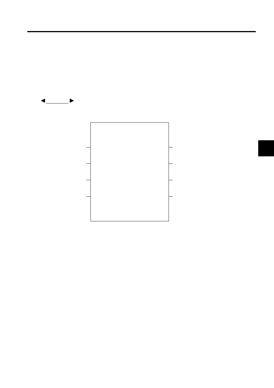
Fig. 3.7 shows the graphic representation of a function when the following function is
defined: Function name = TEST, number of inputs = 4, number of address inputs = 1, and
number of outputs = 4.
Fig. 3.7 Graphic Representation of a Function 1 (Example)
Note: 1. After creating the graphic representation of the function, define the
data types of the function inputs, outputs, and address inputs.
2. Three data types can be defined: Bit, integer, and long integer.
3. When the data types are defined, the system automatically allocates
inputs to the X registers, outputs to the Y registers, and address
inputs to the A registers.
EXAMPLE
TEST
IN_01
IN_05
OUT_01
IN_02
IN_03
IN_04
OUT_02
OUT_03
OUT_04