Four-axis system configuration example – Yaskawa MP920 User's Manual Design User Manual
Page 70
Advertising
2 MP920 Specifications and System Configuration
2.2.2 Overall Configuration
2-44
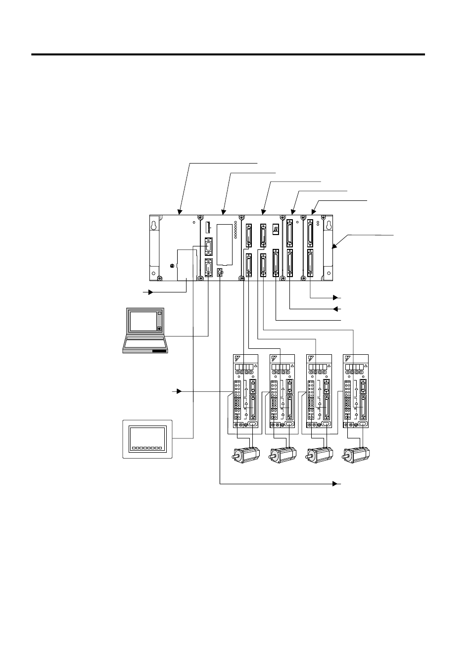
Four-axis System Configuration Example
Up to four axes can be controlled using SVA-01A, DI-01, and DO-01 Modules. Up to 128
I/O points, 64 input points, and 64 output points can be used. The following illustration
shows a 4-axis system configuration example.
SW1
L.RST
RUN
INIT
TEST
MULTI
FLASH
M.RST
ON
OFF
ON
1
2
3
4
5
6
7
8
PORT2
PORT1
CN1
RLY OUT
BATTERY
RDY
PRT1
RUN
ALM
ERR
BAT
ALM
PRT2
MP920 CPU-01
SVA-01
CN1
CN3
CN2
CN4
STATUS
CN5
DI-01
CN1
CN2
RUN
DO-01
CN1
CN2
RUN
FUSE
PS-03
DC24V
POWER
TB1
+24V
0V
FG
SG
24 VDC
External outputs
External inputs
Machine I/O signals
Contact output during RUN
100 VAC
SERVOPACKs
Motors
MPE720
Mounting Base
MB-02
Power Supply Module
CPU Module
Servo Module
Input Module
Output Module
Panel
Advertising