Yaskawa MP920 User's Manual Design User Manual
Page 134
4 Motion Control
4.2.4 Phase Control Mode
4-20
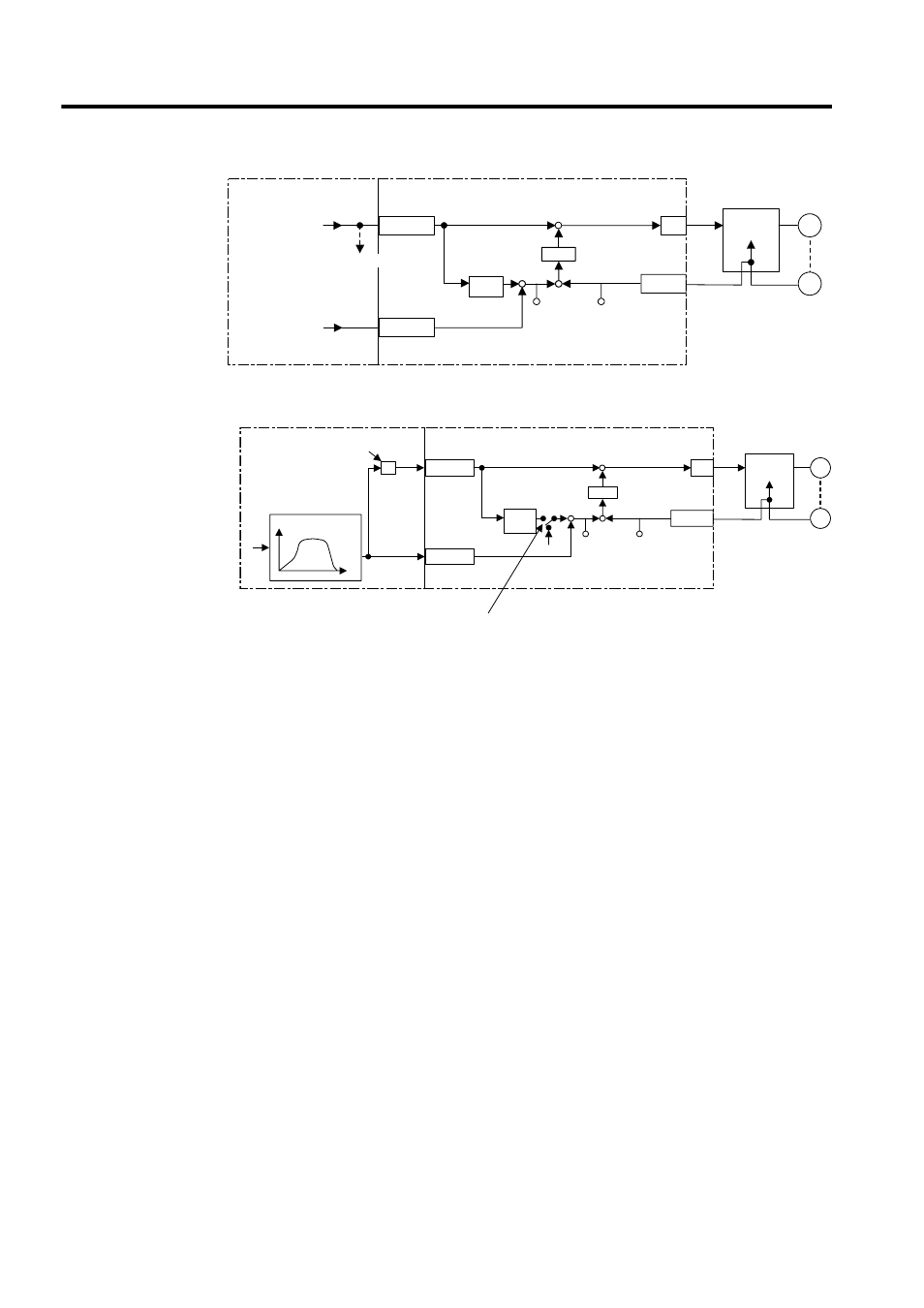
Fig. 4.8 Block Diagram of Phase Control Loop
Fig. 4.9 Block Diagram of Electronic Cam Control Loop
The electronic cam control loop is processed in the SVA Module. Therefore, the user can eas-
ily control the electronic cam simply by selecting the phase control mode on the CPU Mod-
ule and providing the required parameters for the SVA Module.
OWCO15
D/A
PI
OLCO16
NREF
PHBIAS
M
PG
+
+
-
+
+
APOS
IL
08
SVA Module
CPU Module
±
ε
CPOS
IL
02
Standard speed
reference setting
To other machine
Integra-
tion
Counter
Servo driver
Speed
control
Position compensa-
tion setting
D/A
PI
M
PG
+
+
-
APOS
IL
08
CPOS
IL
02
SVA Module
X
S
CPU Module
OWCO15
OLCO16
NREF
PHBIAS
±
ε
One scan change
calculation
Position reference
generation
Position
reference
When Phase Reference Generation Operation Disable
(bit 7 of OWC000) turns ON, the integral circuit is cut.
Counter
Servo driver
Speed
control
Integra-
tion
θ
θ