2 217 i/f communications module (217if), Led indicators – Yaskawa MP920 User's Manual Design User Manual
Page 315
5 Modules
5.6.2 217 I/F Communications Module (217IF)
5-120
5.6.2
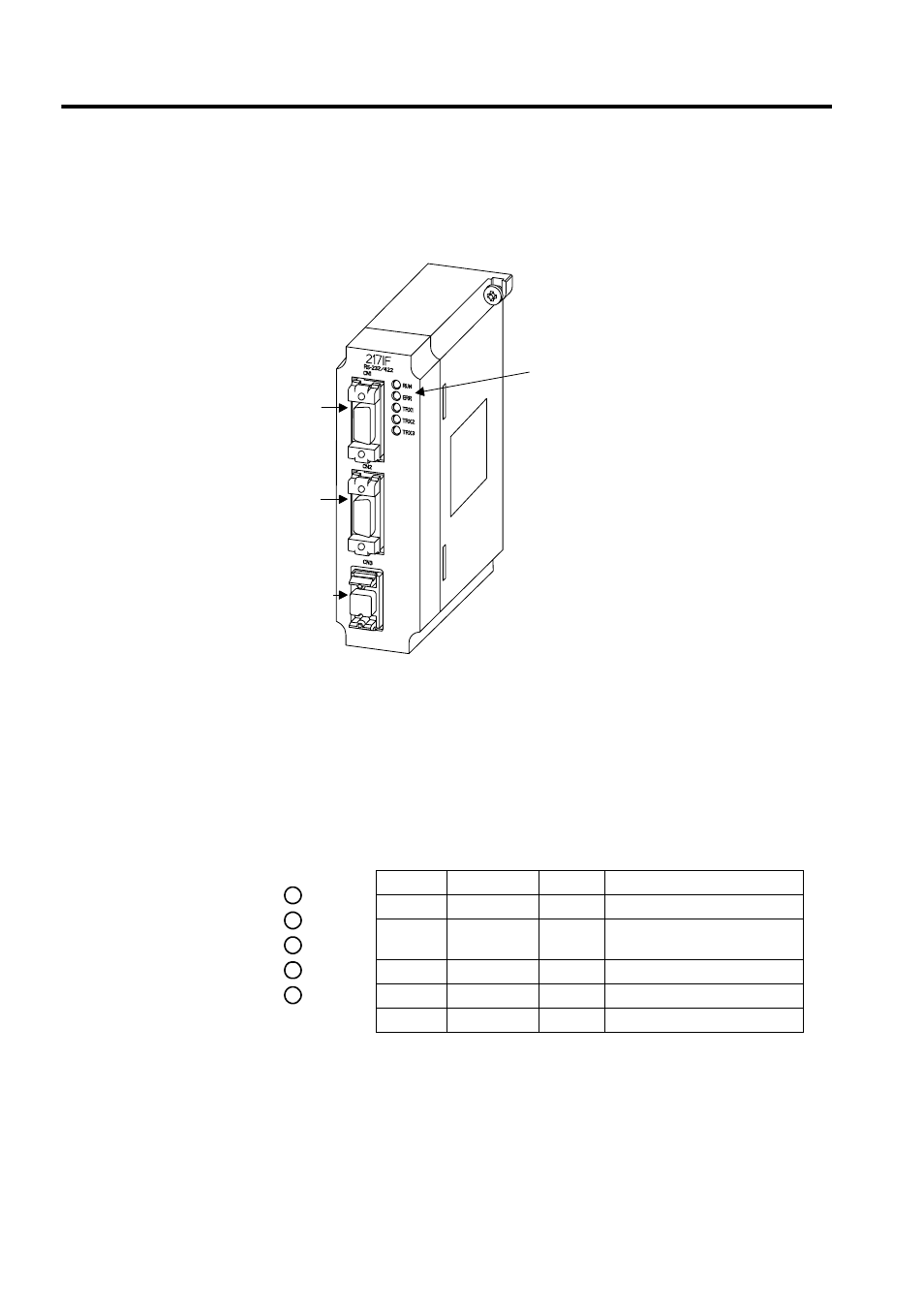
217 I/F Communications Module (217IF)
The following illustration shows the appearance of the 217IF Communications Module.
The details of each part of the 217IF Module are described below.
LED Indicators
While the 217IF Module is operating normally, the RUN LED indicator is lit and the ERR
LED indicator is unlit. When a failure occurs, the RUN lights off and the ERR lights up or
blinks. The TX1, TX2, or TX3 LED indicator is lit while the corresponding port is transmit-
ting data.
Indicator
Name
Color
Status When Lit
RUN
RUN
Green
Normally operating
ERR
ERROR
Red
Failure occurrence (lights/
blinks)
TX1
CN1TX/RX
Green
217IF CN1 transmitting data
TX2
CN2TX/RX
Green
217IF CN2 transmitting data
TX3
CN3TX/RX
Green
217IF CN3 transmitting data
LED
indicators
RS-232C
port 1
CN1
RS-232C
port 2
CN2
RS-422/485
port
CN3
RUN
ERR
TX1
TX2
TX3