Important – Yaskawa MP920 User's Manual Design User Manual
Page 226
5.3 I/O Modules
5-31
5
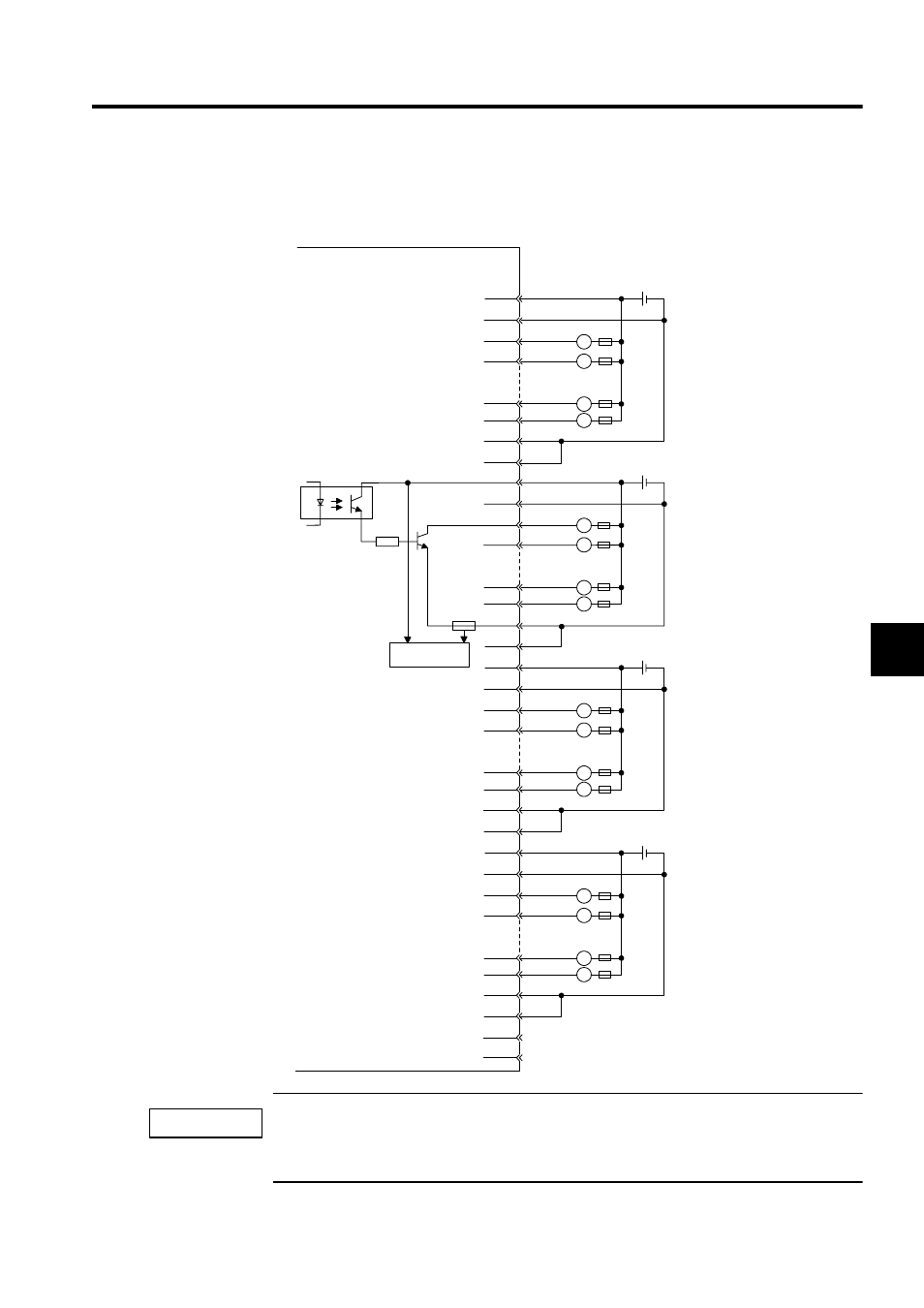
An example of connections to the CN2 connector and an output circuit for the DO-01 Output
Module are shown below.
A fuse is inserted in the output common line of the DO-01 Modules as a protective circuit. If the output
short-circuit is incomplete, there is a risk that the fuse may not blow. Insert a protective element, such
as a fuse, for each output as shown in the above illustration.
7
32
8
33
11
36
13
12
37
38
14
39
17
42
18
43
19
44
20
45
23
48
24
49
25
50
CN2 connector pin
numbers
1
26
2
27
5
30
6
31
L
L
L
L
L
L
L
L
L
L
L
L
L
L
L
L
JEPMC-IO210
+ -
24 VDC
+ -
24 VDC
+ -
24 VDC
+ -
24 VDC
Fuse
Photocoupler
Blown fuse
detection circuit
Output 33
Fuse
Output 34
Output 39
Output 40
Output 41
Output 42
Output 47
Output 48
Output 49
Output 50
Output 55
Output 56
Output 57
Output 58
Output 63
Output 64
.
.
.
.
.
.
.
.
.
.
.
.
IMPORTANT