Specifications of devicenet connector cn1 – Yaskawa MP920 User's Manual Design User Manual
Page 326
5.6 Communications Modules
5-131
5
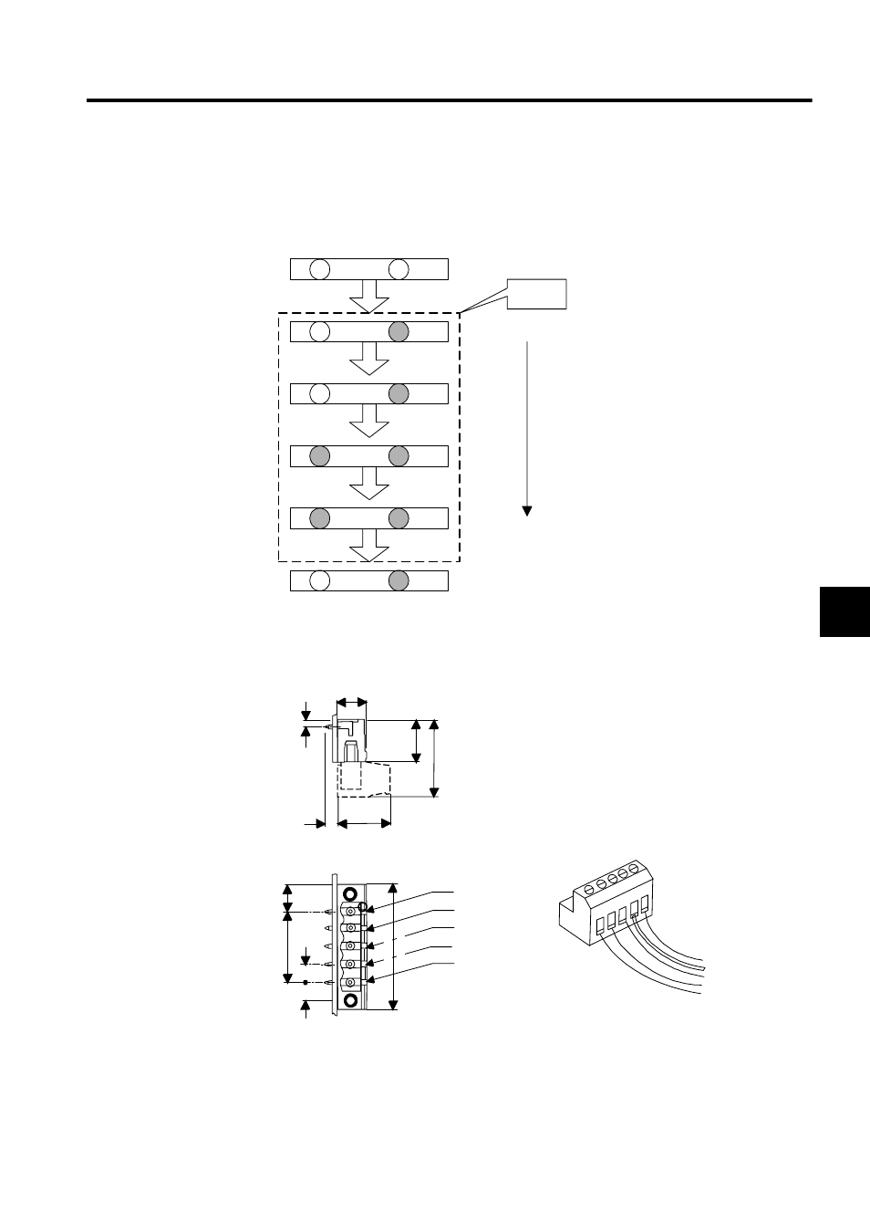
The LED test sequence after the power is turned ON is shown below. Check to see if there is
a LED failure according to the status of each LED. The time required for the LED test is 1
second.
Fig. 5.3 LED Display Status during LED Check
Specifications of DeviceNet Connector CN1
Fig. 5.4 DeviceNet Connector CN1
Unlit
Unlit
Unlit
Unlit
Unlit
Lit in
green
Lit in
green
Lit in
green
Lit in
green
Lit in
green
Lit in
red
Lit in
red
0.25 s
0.25 s
0.25 s
0.25 s
Power OFF
LED test starts
1 sec
LED test completed
NS
MS
Module
startup
Open plug (5-pin, male) conforming to DeviceNet specification
Red
White
Bare wire
Blue
Black
Network-side connector (female)
Units: mm
5
5
20.32
(5.08)
(7.62)
7.5
(5.08)
15
12
3.5
2
8.3
22
3 SHIELD
5 V+
4 CAN_H
3 drain
2 CAN_L
1 V-
(35.32)
(35.56)
1 V-
5 V+
2 CAN_L
4 CAN_H