Yaskawa MP920 User's Manual Design User Manual
Page 317
5 Modules
5.6.2 217 I/F Communications Module (217IF)
5-122
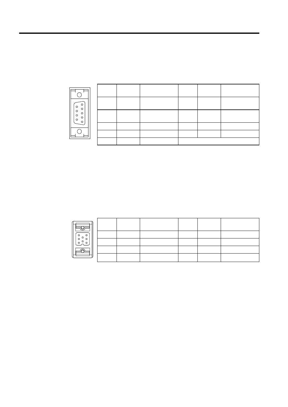
Specifications of RS-232C Ports 1 and 2 (CN1 and CN2)
The following table shows the name and function of the CN1/CN2 connector pins.
For the connector on the Module, D-sub 9-pin female connector 17LE-13090-27 (D2BC)
manufactured by DDK Ltd. is used.
Use a D-sub 9-pin male connector 17JE-23090-02 (D8B) manufactured by DDK Ltd. for the
cable-end connector.
Specifications of RS-422/485 Port (CN3)
The following table shows the name and function of the CN3 connector pins.
* A terminator is provided on the positive (+) polarity side.
For the connector on the Module, MR-8RFA4 (G) manufactured by Honda Tsushin Kogyo
Co., Ltd. is used.
Use an MR-8M (G) (case: MR-8L) connector for the cable-end connector.
Table 5.5 RS-232 Ports (CN1 and CN2)
Pin No.
Signal
Name
Function
Pin No.
Signal
Name
Function
1
FG
Protective ground-
ing
6
DSR
Data set ready
2
SD
Send data
7
SG
Signal grounding
(0 V)
3
RD
Receive data
8
N.C
Not connected
4
RS
Request to send
9
DTR
Data
5
CS
Ready to send
Table 5.6 RS-422/485 Port (CN3)
Pin No.
Signal
Name
Function
Pin No.
Signal
Name
Function
1
RX (-)
Receive data (-)
5
TRX (+)
*
2
RX (+)
Receive data (+)
6
TX (-)
Send data (-)
3
N.C
Not connected
7
TX (+)
Send data (+)
4
RXR (+)
*
8
SG
Signal grounding