Yaskawa MP920 User's Manual Design User Manual
Page 261
5 Modules
5.4.2 AO-01 Analog Output Module
5-66
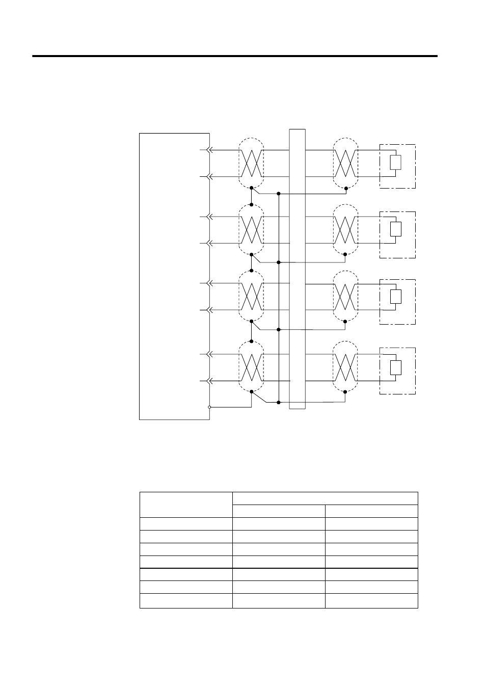
AO-01 Module Connection Example
Output Characteristics
Click either -10 to +10 V Mode or 0 to 10 V Mode in the AO-01 Configuration Window
from CP-717 software.
* Linearity cannot be guaranteed if the analog input is more than 10.0 V.
Output Register
Analog Input
-10 to +10 V Mode
0 to 10 V Mode
-32768
-10.5 V*
−
-31276
-10.0 V
−
-15638
-5.0 V
−
0
0.0 V
0.0 V
15638
+5.0 V
+5.0 V
31276
+10.0 V
+10.0 V
32767
+10.5 V
*
+10.5 V*
AO-01
L
L
L
L
1
3
2
4
6
8
7
9
-10 to +10 V
-10 to +10 V
External device
External device
Shielded twisted-
pair cable
Shielded multi-
core cable
-10 to +10 V
External device
-10 to +10 V
External device
Junction terminal block
Alalog output 1
Ground 1
Alalog output 2
Ground 2
Alalog output 3
Ground 3
Alalog output 4
FG (connector shell)
Ground 4