Yaskawa MP920 User's Manual Design User Manual
Page 421
8 Controlled Axis Support Functions
8-4
The following parameters are related to the electronic gear.
Parameter
No.
Name
Description
Default
18
Number of Digits
Below Decimal
Point
The minimum reference unit is determined by this parameter and
Reference Unit Selection in the Motion Controller Function Selec-
tion Flags (b0 to b3).
Parameter set values are described below.
3
19
Machine Rota-
tions Per Refer-
ence Unit
Sets the amount a load moves (reference unit) per load axis rota-
tion.
Setting range: 1 to 2
31
-1
10000
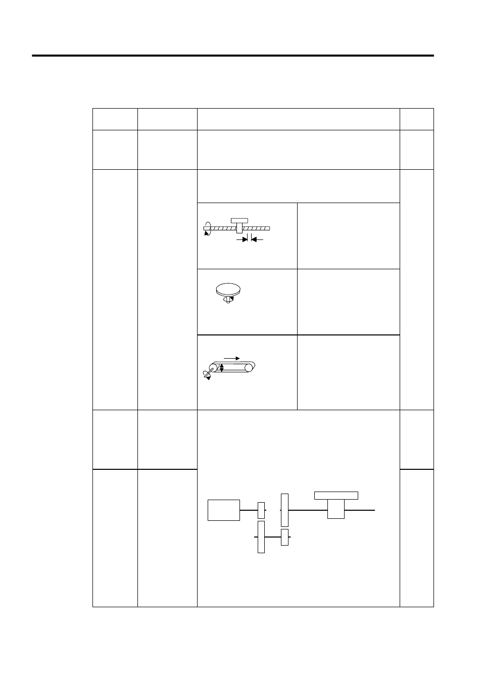
Ball screw
Ball screw pitch = 10 mm,
Reference Unit Selection = mm,
Number of Digits Below
Decimal Point = 3
↓
Set the Distance Travelled Per
Machine Rotation to 10,000.
Rotating table
One table rotation = 360
°,
Reference Unit Selection = deg,
Number of Digits Below
Decimal Point = 3
↓
Set the Distance Travelled Per
Machine Rotation to 360,000.
Belt
Roller 1 rotation = 360
°,
Reference unit selection = mm,
Number of Digits Below
Decimal Point = 3
↓
Set the Distance Travelled Per
Machine Rotation to
πD ×
1,000.
20
Servomotor
Gear Ratio
These parameters are used to set the gear ratio for the Servomotor
and load.
Set the following at values that will allow the load shaft to rotate n
times when the Servomotor shaft rotates m times.
• Servomotor Gear Ratio = m
• Load Gear Ratio = n
1
21
Load Gear Ratio Setting example
In the preceding diagram, the deceleration ratio, n/m = 3/7
× 4/9 =
4/21
Consequently, set the Servomotor Gear Ratio to 21 and the Load
Gear Ratio to 4.
1
Ball screw pitch = 10 mm
10
One rotation 360
°
π D
D
m (Servomotor
shaft rotations)
7 rotations
4 rotations
9 rotations
n (load shaft rotations)
3 rotations