2 execution control of parent drawings – Yaskawa MP920 User's Manual Design User Manual
Page 85
3.4 User Programs
3-11
3
Table 3.5 gives details of the number of drawings for each type of drawing.
3.4.2
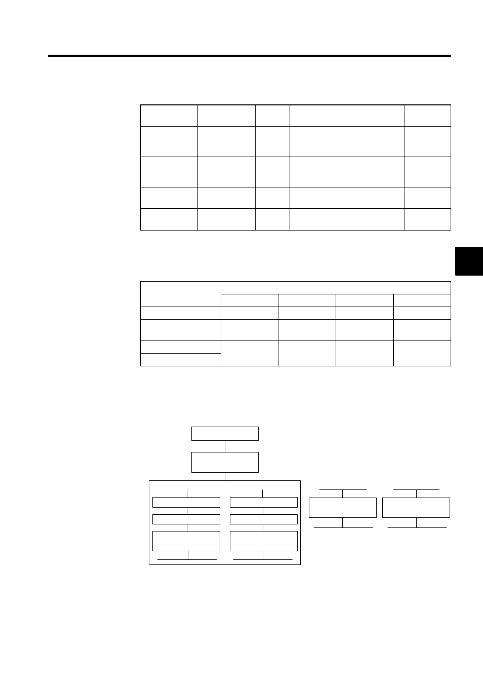
Execution Control of Parent Drawings
Each drawing is executed based on its priority level, as shown in Fig. 3.2.
Fig. 3.2 Execution Control of Parent Drawings
Table 3.4 Types and Priority Levels of Parent Drawings
Type of Parent
Drawing
Role of Drawing
Priority
Level
Execution Condition
Number of
Drawings
DWG.A
Startup process
1
Started when power is turned ON
(executed once only when the power
is turned ON)
64
DWG.I
Interrupt process
2
Executed by external interrupts, such
as Optional Module DI interrupts or
counter interrupts.
64
DWG.H
High-speed scan
process
3
Started at a fixed interval (executed
during each high-speed scan)
200
DWG.L
Low-speed scan
process
4
Started at a fixed interval (executed
during each low-speed scan)
500
Table 3.5 Details of Drawings
Drawing
Number of Drawings
DWG.A
DWG.I
DWG.H
DWG.L
Parent Drawing
1 (A)
1 (I)
1 (H)
1 (L)
Operation Error
Drawing
1 (A00)
1 (I00)
1 (H00)
1 (L00)
Child Drawings
Maximum total
of 62 drawings
Maximum total
of 62 drawings
Maximum total
of 198 drawings
Maximum total
of 498 drawings
Grandchild Drawings
: A, I, H, L
Power ON
DWG.A
Startup drawing
During each low-speed scan
All outputs
All inputs
DWG.H
High-speed scan
process drawings
DWG.L
Low-speed scan
process drawings
Operation error
Continue with
original process
All outputs
All inputs
Interrupt signal
Continue with
original process
DWG. 00
Operation error
drawing
DWG. I
Interrupt drawing
During each high-speed scan