Yaskawa MP920 User's Manual Design User Manual
Page 540
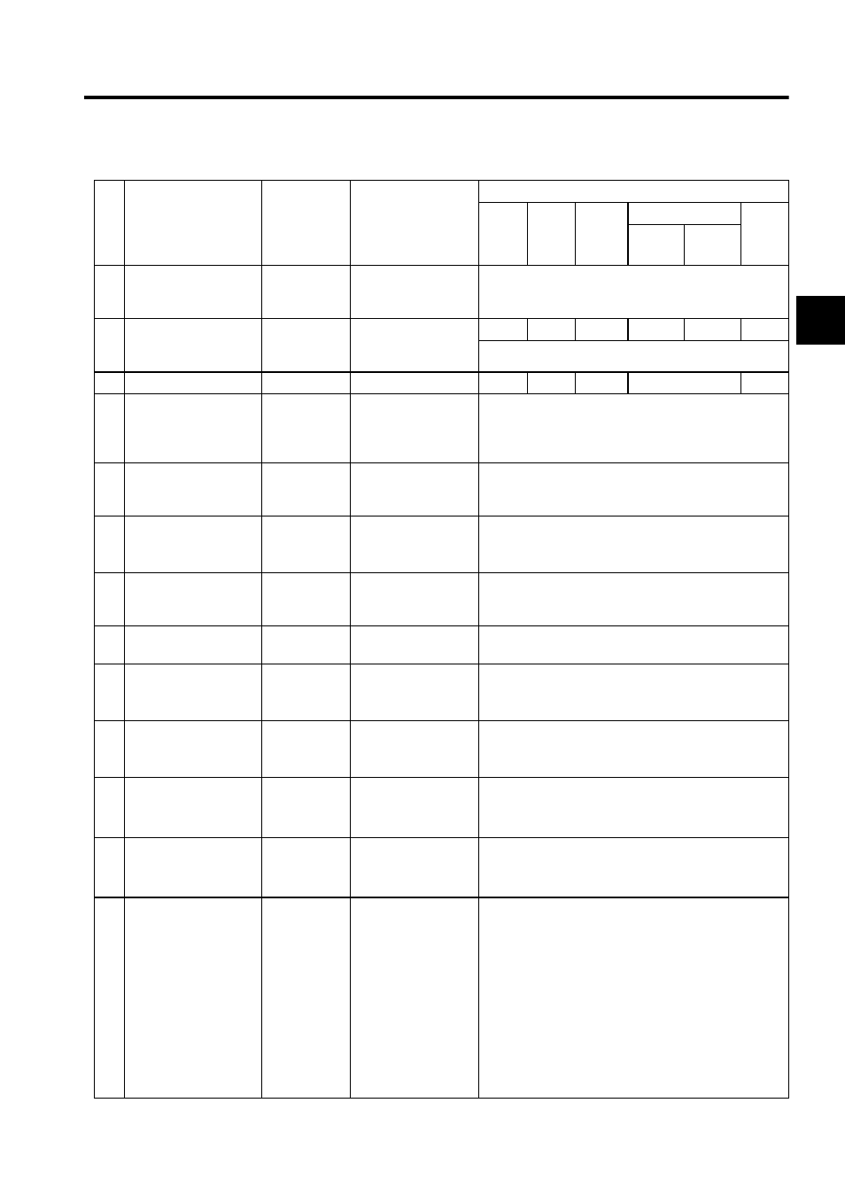
A.3 Parameter List
A-25
A
13 DI Latch Signal
Selection
(DIINTSEL)
0 or 1
(Default = 0)
0: DI input signal
1: C pulse input signal
0 (DI input signal)
(Set an appropriate value.)
14 Additional Function
Selections
(AFUNCSEL)
Set by bit
(Default =
0080H)
See 7.2.1 Motion
Fixed Parameters.
0080H 0080H 0080H
0000H
0080H
0080H
(Set an appropriate value.)
16 Not Used
−
−
−
−
−
−
17 Motion Controller
Function Selection
Flags
(SVFUNCSEL)
Set by bit
(Default =
0000H)
See 7.2.1 Motion
Fixed Parameters.
0000H
(Set an appropriate value.)
18 Number of Digits
Below Decimal Point
(DECNUM)
0 to 5
(Default = 3)
Set the number of dig-
its below the decimal
point for commands.
3
19 Distance Traveled Per
Machine Rotation
(PITCH)
1 to 2
31
-1
(Default =
10000)
1 = 1 reference unit
10000
21 Servomotor Gear
Ratio
(GEAR_MOTOR)
1 to 65535
(Default = 1)
1 = 1 rotation
1
22 Machine Gear Ratio
(GEAR_MACHINE)
1 to 65535
(Default = 1)
1 = 1 rotation
1
23 Infinite Length Axis
Reset Position
(POSMAX)
1 to 2
31
-1
(Default =
360000)
1 = 1 reference unit
360000
25 Maximum Number of
Absolute Encoder
Turns (MAXTURN)
1 to 2
31
-1
(Default =
99999)
1 = 1 rotation
99999
27 Positive Software
Limit
(SLIMP)
-2
31
to 2
31
-1
(Default =
2
31
-1)
1 = 1 reference unit
2
31
-1
29 Negative Software
Limit
(SLIMN)
-2
31
to 2
31
-1
(Default =
-2
31
)
1 = 1 reference unit
-2
31
31 Zero Point Return
Method
(ZRETSEL)
0 to 7
(Default = 0)
0: DEC1 + C-phase
pulse
1: ZERO
2: DEC1 + ZERO
3: C-phase pulse
4: DEC2 + ZERO
5: DEC1 + LMT
+ ZERO
6: DEC2 + C-phase
pulse
7: DEC1 + LMT
+ C pulse
0 (DEC1 + C-phase pulse)
(cont’d)
No.
Name
Setting
Range
Meaning
Standard Setting
Zero
Point
Return
Speed Torque
Position
Phase
Position
1
*1
Position
2
*2