Yaskawa MP920 User's Manual Design User Manual
Page 372
6 System Startup
6.2.5 Ladder Logic Programs
6-42
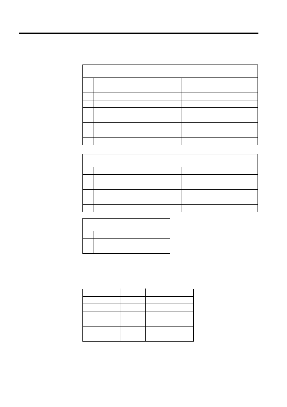
A detailed description of the registers is given in the following table.
Registers in Subroutine Logic Programs (H01.01, H01.02)
The following table shows the configuration of the group work registers used by the subrou-
tine logic programs.
Program Status
(DW00100)
Program Control Signal
(DW00101)
b0
Program running
b0
Program start request
b1
Program paused
b1
Program pause request
b2
(Used by the system.)
b2
Program forced stop request
b3
(Used by the system.)
b3
Program debugging mode selection
b4
Program being debugged
b4
Program debugging start request
b8
Program alarm generated
b5
Alarm reset request
bB
Debugging mode (EWS debugging)
b8
Skip 1 information
bE
Main program duplication error
b9
Skip 2 information
bF
Main program number exceeded error
−
−
Automatic, Common
(DW00102)
Manual, Common
(DW00103)
b0
Stopped for emergency
b0
Operating manually
b1
Status history
−
−
b2
Debugging start history
−
−
b3
Automatic mode status OFF request
−
−
b4
Manual mode status OFF request
−
−
b5
Program start request
−
−
Manual Status
(DW00104)
b0
Axis alarm generated
b1
Command duplication command alarm
b2
Operating manually
Register Number
Size
Description
DW00100
1 word
Manual status
DW00101
1 word
Command/Response
DW00102
1 word
FEED status
DW00103
1 word
STEP status
DW00104
1 word
ZRET status
DW00105
1 word
ZSET status