Important – Yaskawa MP920 User's Manual Design User Manual
Page 253
5 Modules
5.4.1 AI-01 Analog Input Module
5-58
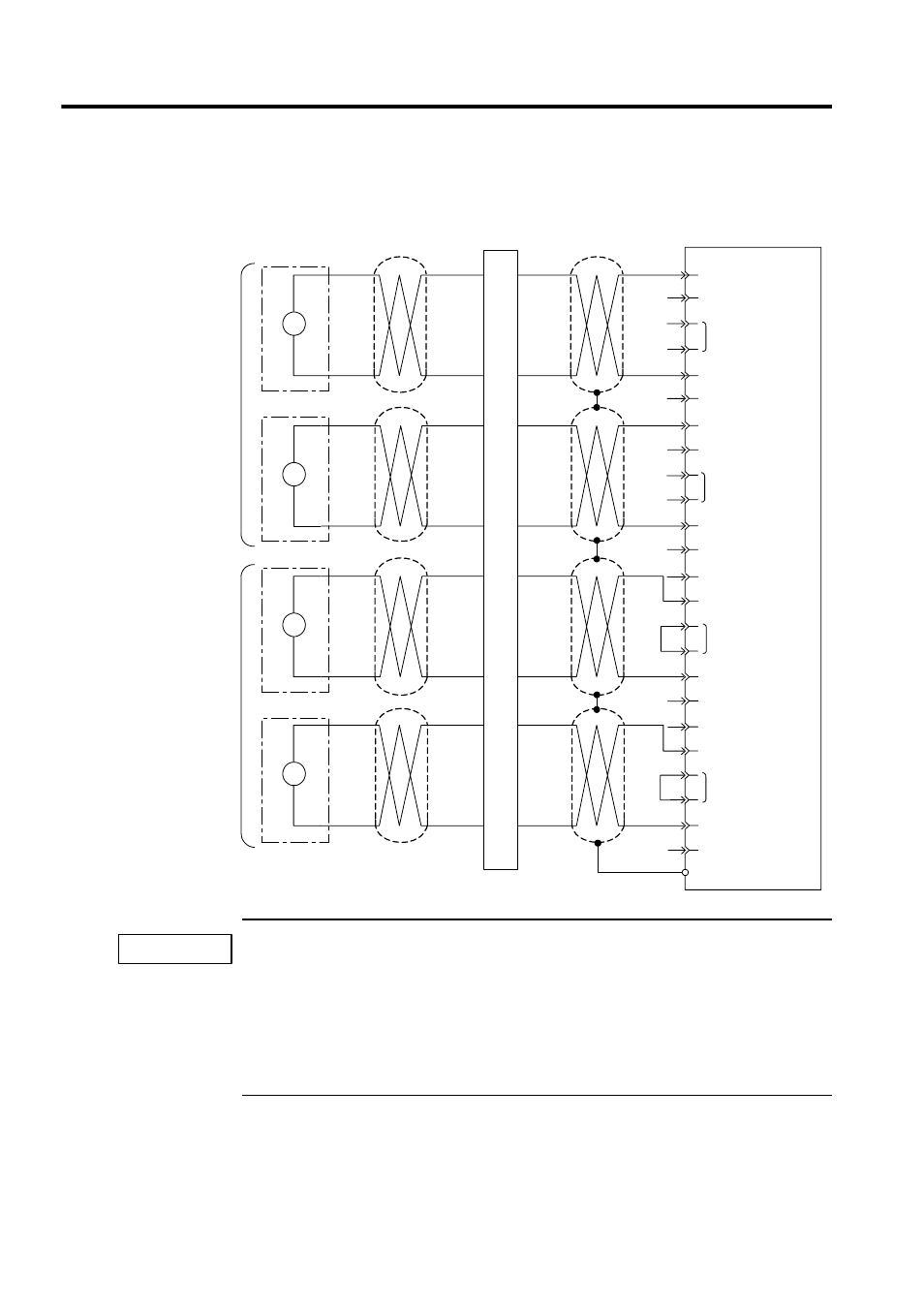
AI-01 Module Connection Example: Voltage Input Mode
1. When voltage input mode is used, leave the mode switch terminals open and do not connect any-
thing to the current input terminals.
2. Use standard JEPMC-W6080- Cable to connect external devices to the AI-01 Module. Use
junction terminal blocks to allow for differences in distances from the AI-01 Module will be differ-
ent.
3. When current input mode is used, short-circuit the mode switch terminal and do not connect any-
thing to the the voltage input terminals.
AI-01
1
3
14
16
2
15
5
18
4
12
7
9
20
22
8
21
23
25
11
24
10
-10 to +10 V
-10 to +10 V
6
17
19
External device
External device
Shielded twisted-
pair cable
Shielded multi-
core cable
V
V
-10 to +10 V
External device
V
-10 to +10 V
External device
V
Voltage Input Mode
Current Input Mode
Junction terminal block
Voltage input 1
Ground 1 (signal)
Ground 1 (shield)
Current input 1
Mode switch 1
Voltage input 2
Ground 2 (signal)
Ground 2 (shield)
Current input 2
Mode switch 2
Voltage input 3
Ground 3 (signal)
Ground 3 (shield)
Current input 3
Mode switch 3
Voltage input 4
Ground 4 (signal)
Ground 4 (shield)
FG (connector shell)
Current input 4
Mode switch 4
IMPORTANT