Yaskawa MP920 User's Manual Design User Manual
Page 316

5.6 Communications Modules
5-121
5
The LED indicators indicate error or failure occurred in the Module as shown below.
Note: The number in parentheses ( ) indicates the number of blinkings.
RS-232C Ports 1 and 2 (CN1 and CN2)
RS-422/485 Port (CN3)
Error/Failure
Details of Error/Failure
LED Indicators
RUN
ERR
TX
RX
PROM
checksum error
PROM checksum error
was detected during
online self-diagnosis.
Unlit
Blink-
ing (1)
Depends on the
conditions.
SRAM error in Module
A hardware fault was
detected during online
self-diagnosis.
Unlit
Blink-
ing (2)
Unlit
Unlit
CPU
interface error
An error in the data
transmission with CPU
was detected during self-
diagnosis.
Unlit
Blink-
ing (3)
Unlit
Unlit
Transmission error
Transmission data error
Lit
Lit
Depends on the
conditions.
Watchdog timeout error
Watchdog timeout
Unlit
Lit
Depends on the
conditions.
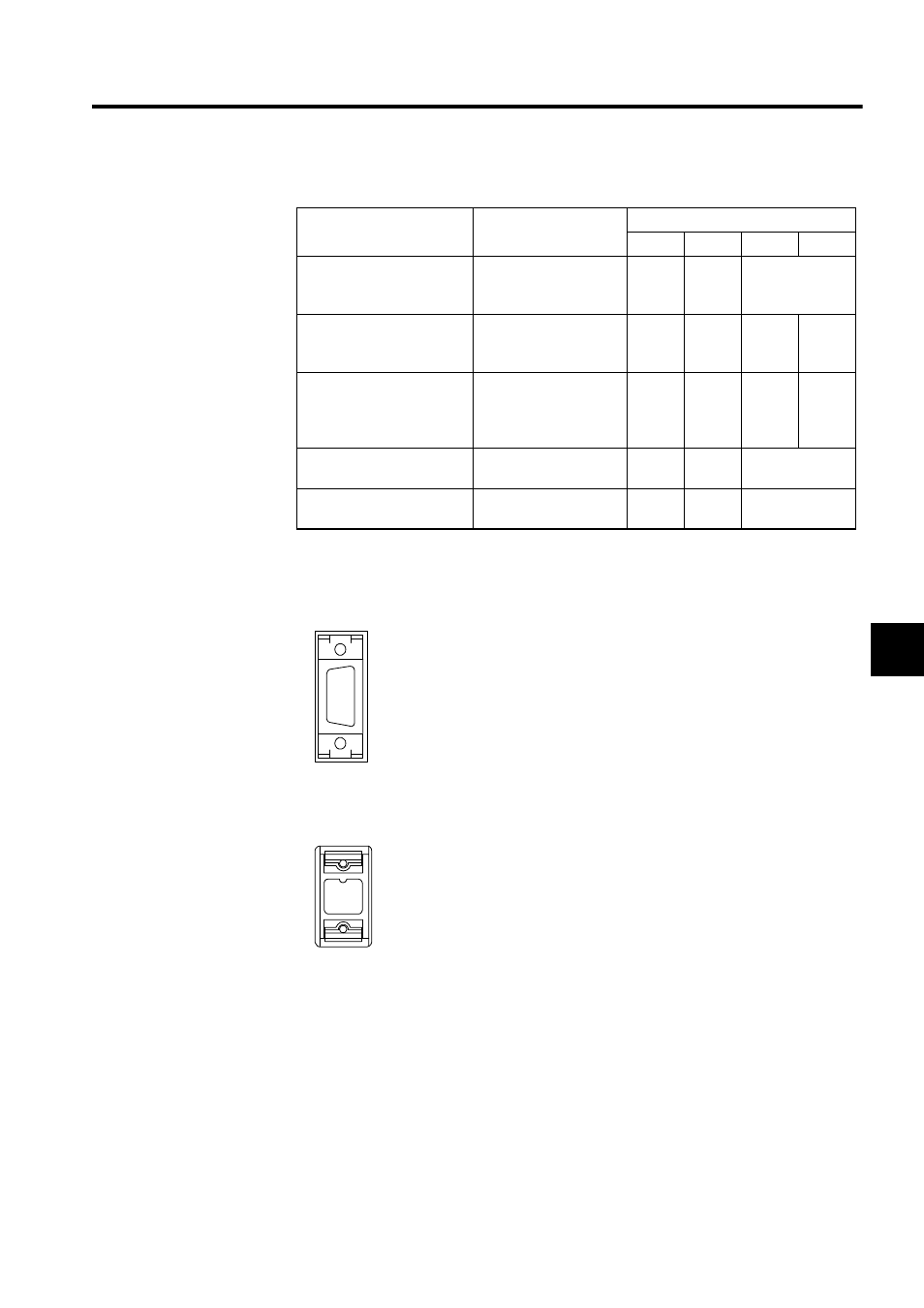
The CN1 and CN2 are used to connect devices with RS-232C inter-
face.
No standard cable available.
The CN3 is used to connect a device with RS-422 or RS-485 inter-
face.
No standard cable available.