External i/o cables models, Appearance cable connection diagram, Important – Yaskawa MP920 User's Manual Design User Manual
Page 279
Advertising
5 Modules
5.5.1 Servo Module (4-axis)
5-84
The following SERVOPACK parameters must be set when the brake signal is used.
The standard cable is made to connect the SEN signal to Pin 20.
• Select whether the BK signal will be output from pins 27 and 28 of the CN1 connector.
Cn-2D (OUTSEL output signal selection) = 4
↑1BK output from pins 27 and 28 of CN1
• Cn-12 (Time delay from brake command until Servo turns OFF)
Cn-15 (Brake output speed level for motor rotation time)
Cn-16 (Brake output timing for motor rotation time)
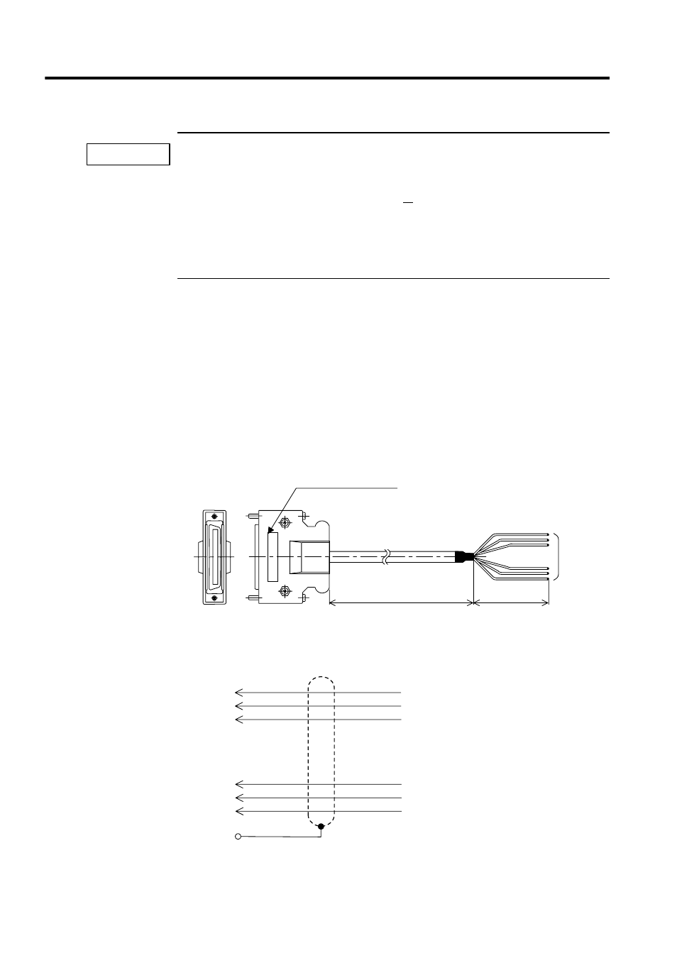
External I/O Cables
Models
JEPMC-W6060-05: 0.5 m
JEPMC-W6060-10: 1.0 m
JEPMC-W6060-30: 3.0 m
Appearance
Cable Connection Diagram
IMPORTANT
L
150
50 loose
wires
NP: JEPMC-W6060-05
Body FG
48
49
50
1
2
3
48
49
50
1
2
3
Connector
Label No.
.
.
.
.
.
Advertising