Yaskawa MP920 User's Manual Design User Manual
Page 304
5.5 Motion Modules
5-109
5
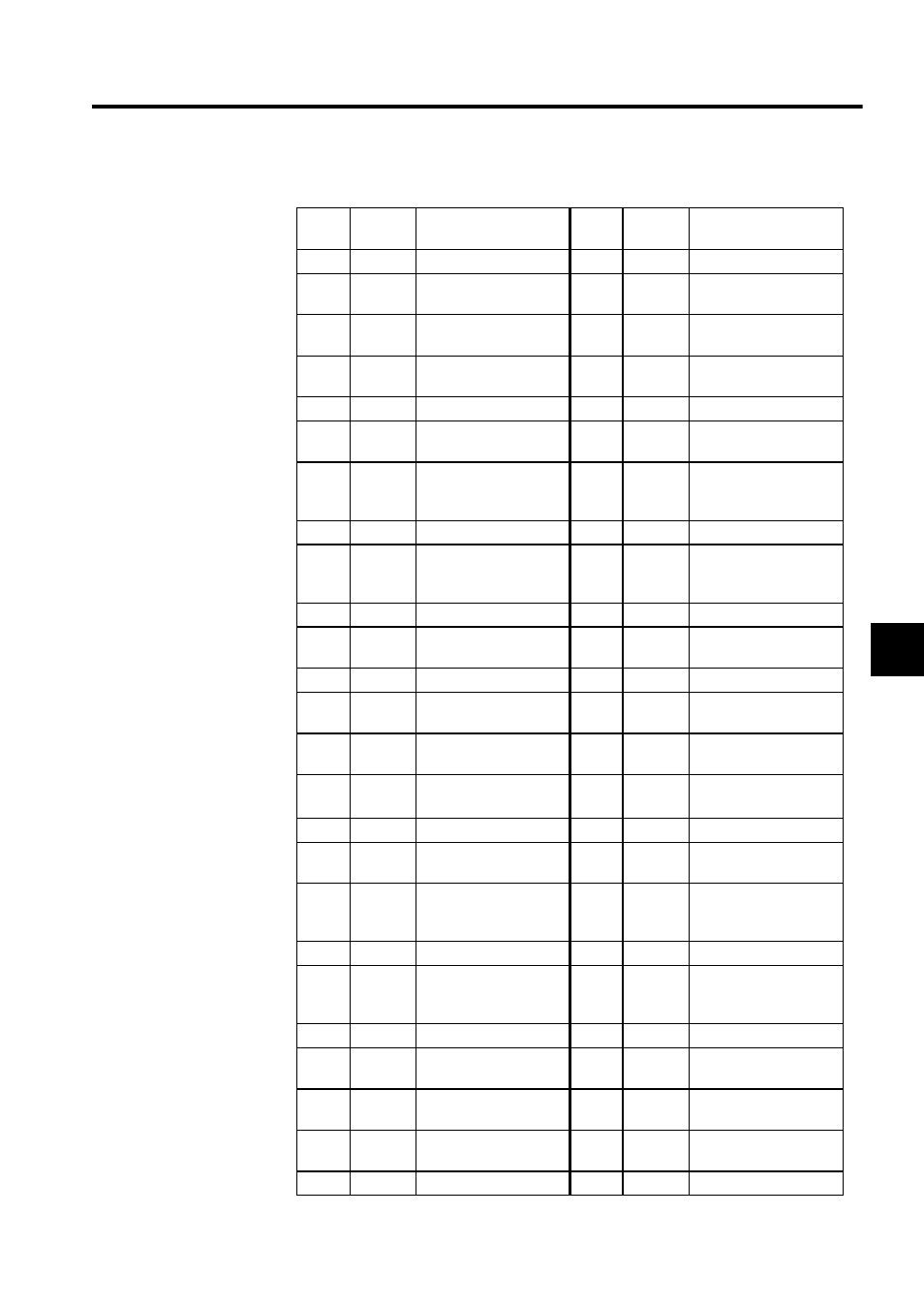
The following table shows the name and function of the CN1 connector pins.
Pin
No.
Signal
Name
Function
Pin
No.
Signal
Name
Function
1
NC
26
NC
2
CW1+
CH1 CW output (+)
27
CCW1+
(sign+)
CH1 CW (sign)
output (+)
3
CW1-
CH1 CW output (-)
28
CCW1-
(sign-)
CH1 CW (sign)
output (-)
4
PO_0V
Common with
Module 0 V
29
PO_0V
Common with
Module 0 V
5
DI1_0+
CH1 input _0 (+)
30
NC
6
DI1_0-
(24V)
CH1 input _0 (-)
24 V
31
DO1_0
CH1 DO output _0
7
DI1_0-
(5/12V)
CH1 input _0 (-)
5 V/12 V
32
DO1_0-
(with
resistor)
CH1 DO output _0
(with 1.5 k
Ω)
8
DI1_1
CH1 input _1
33
DO1_1
CH1 DO output _1
9
DI1_2
CH1 input _2
34
DO1_1
(with
resistor)
CH1 DO output _1
(with 1.5 k
Ω)
10
DI1_3
CH1 input _3
35
DO1_2
CH1 DO output _2
11
DI1_4
CH1 input _4
(Emergency stop)
36
DO1_3
CH1 DO output _3
12
NC
37
NC
13
CW2+
CH2 CW output (+)
38
CCW2+
(sign+)
CH2 CW (sign)
output (+)
14
CW2-
CH2 CW output (-)
39
CCW2-
(sign-)
CH2 CW (sign)
output (-)
15
PO_0V
Common with
Module 0 V
40
PO_0V
Common with
Module 0 V
16
DI2_0+
CH2 input _0 (+)
41
NC
17
DI2_0-
(24V)
CH2 input _0 (-)
24 V
42
DO2_0
CH2 DO output _0
18
DI2_0-
(5/12V)
CH2 input _0 (-)
5 V/12 V
43
DO2_0
(with
resistor)
CH2 DO ourput _0
(with 1.5 k
Ω)
19
DI2_1
CH2 input _1
44
DO2_1
CH2 DO output _1
20
DI2_2
CH2 input _2
45
DO2_1-
(with
resistor)
CH2 DO output _1
(with 1.5 k
Ω)
21
DI2_3
CH2 input _3
46
DO2_2
CH2 DO output _2
22
DI2_4
CH2 input _4
(Emergency stop)
47
DO2_3
CH2 DO output _3
23
24V_1
I/O power supply input
(24 V)
48
24V_1
I/O power supply input
(24 V)
24
0V_1
I/O power supply input
(0 V)
49
0V_1
I/O power supply input
(0 V)
25
NC
50
NC