Module connection examples, Important – Yaskawa MP920 User's Manual Design User Manual
Page 225
5 Modules
5.3.2 DO-01 Output Module
5-30
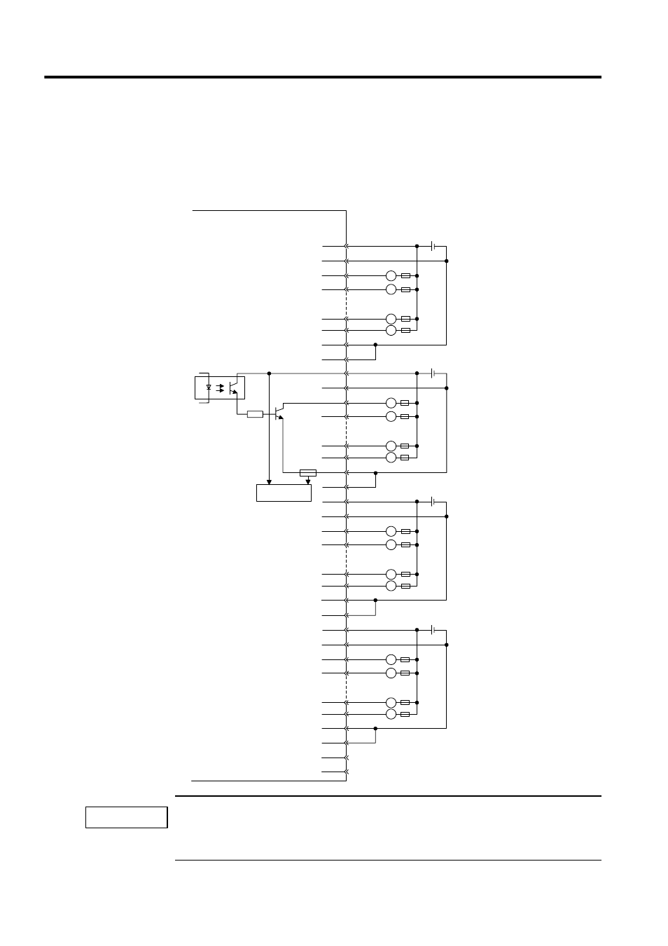
Module Connection Examples
An example of connections to the CN1 connector and an output circuit for the DO-01 Output
Module are shown below.
A fuse is inserted in the output common line of the DO-01 Module as a protective circuit. If the output
short-circuit is incomplete, there is a risk that the fuse may not blow. Insert a protective element, such
as a fuse, for each output as shown in the above illustration.
7
32
8
33
11
36
13
12
37
38
14
39
17
42
18
43
19
44
20
45
23
48
24
49
25
50
1
26
2
27
5
30
6
31
L
L
L
L
Output 1
Output 2
Output 7
Output 8
Output 9
Output 10
Output 15
Output 16
Output 17
Output 18
Output 23
Output 24
Output 25
Output 26
Output 31
Output 32
L
L
L
L
L
L
L
L
L
L
L
L
JEPMC-IO210
CN1 connector
pin numbers
+ -
24 VDC
+ -
24 VDC
+ -
24 VDC
+ -
24 VDC
Fuse
Fuse
Photocoupler
Blown fuse
detection circuit
.
.
.
.
.
.
.
.
.
.
.
.
IMPORTANT