Counter module (cntr-01) – Yaskawa MP920 User's Manual Design User Manual
Page 37
2.1 Specifications
2-11
2
Counter Module (CNTR-01)
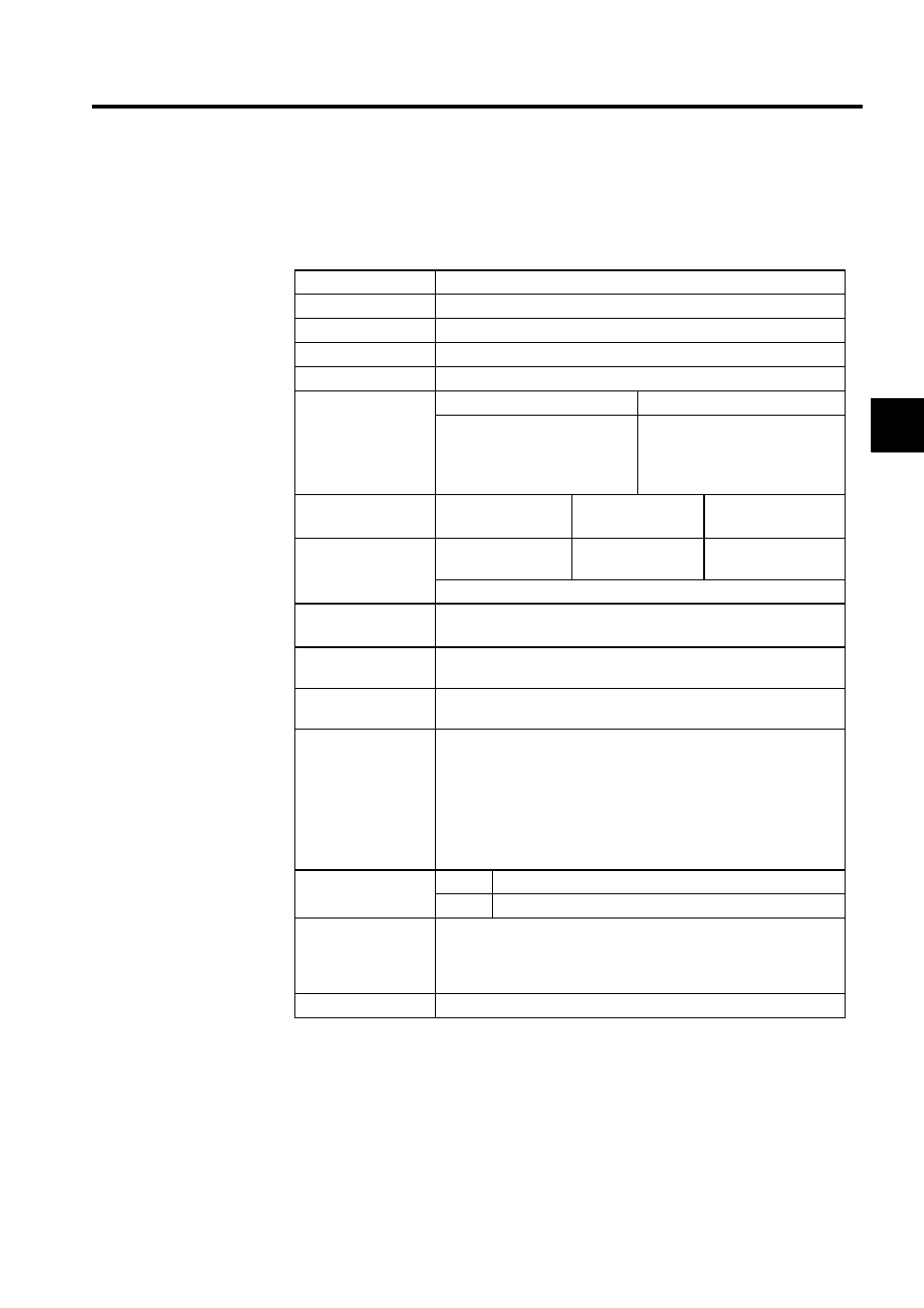
Table 2.9 shows the hardware specifications of the CNTR-01 Counter Module.
Table 2.9 Hardware Specifications of the CNTR-01 Counter Module
Item
Specifications
Name
Counter Module
Model Number
JEPMC-PL200
Description
CNTR-01
Number of Channels 4
Input Circuit
(Software switching)
5-V differential
12-V
Response frequency:2 MHz
RS422 type
Response frequency: 120 kHz
12 V, 7 mA, current sourcing
mode input
Photocoupler insulation
Input Method
(Software switching)
Phases A/B/C
(
×1, ×2, ×4)
Up/Down
(
×1, ×2)
Sign
(
×1, ×2)
Counter Function
(Software switching)
Reversible counter
Interval counter
Frequency
measurement
Frequency: 2 MHz max. (with 5-V differential input)
Coincidence
Interrupt
Output to the CPU Module via the system bus
Outputs the DO at the same time.
Coincidence Output
4 points, 24 V, 50 mA, current sinking mode output, photocoupler insu-
lation
PI Latch Input
4 points, 24 V, 50 mA, current sinking mode output, photocoupler insu-
lation
Indicators
Module status LED indicators
RUN (green): Normally operating/ Unlit in stop status
ERR (red): Normal/ Module failure
COUNT1 (green): CH1 counting up/down
COUNT2 (green): CH2 counting up/down
COUNT3 (green): CH3 counting up/down
COUNT4 (green): CH4 counting up/down
Connectors
CN1
10250-52A2JL (5-V differential input, 4 channels)
CN2
10250-52A2JL (12-V input, 4 channels)
Hot Swapping
(Insert/Remove
while power is being
supplied)
Not allowed
Dimensions (mm)
40
× 130 × 105 (W × H × D)