Yaskawa MP920 User's Manual Design User Manual
Page 363
6.2 System Startup Procedure
6-33
6
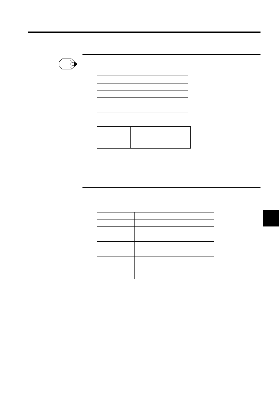
• When the settings are made as shown in g) and h), the following registers will be allocated.
Number of parallel processings (set in the Motion Properties (default = 4))
The position output registers for the number of axes in the group are automatically allocated.
• By default, the group input signals and axis input signals are allocated sequentially starting from
IB00000. When a test must be conducted without connecting the input signal lines, it is conve-
nient to set M registers.
Turning ON or OFF the signals on the Register List Screen has the same effect as using the switch
box.
i) Axis Input Signal
Set as follows in the setting field.
Alarm Output Register
Parallel 1
MW00004
Parallel 2
MW00005
Parallel 3
MW00006
Parallel 4
MW00007
Position Output Register
Axis 01
ML00020
Axis 02
ML00022
Axis 01
Axis 02
Servo ON
IB00010
IB00020
JOG+
IB00011
IB00021
JOG
-
IB00012
IB00022
STEP+
IB00013
IB00023
STEP-
IB00014
IB00024
ZRN
IB00015
IB00025
Set Zero Point
IB00016
IB00026
Stop
IB00017
IB00027
INFO