Yaskawa MP920 User's Manual Design User Manual
Page 206
5.2 CPU Modules
5-11
5
MEMOBUS Ports
Using RS-232C, the CPU Module can communicate with other devices on the MEMOBUS
network through the MEMOBUS ports.
The following transmission devices can be connected to the MEMOBUS ports: Program-
ming Devices, i.e., computers with an RS-232C interface.
The MEMOBUS port connector is a D-sub 9-pin, female connector. Table 5.3 shows the lay-
out of the connector pins and the signal names.
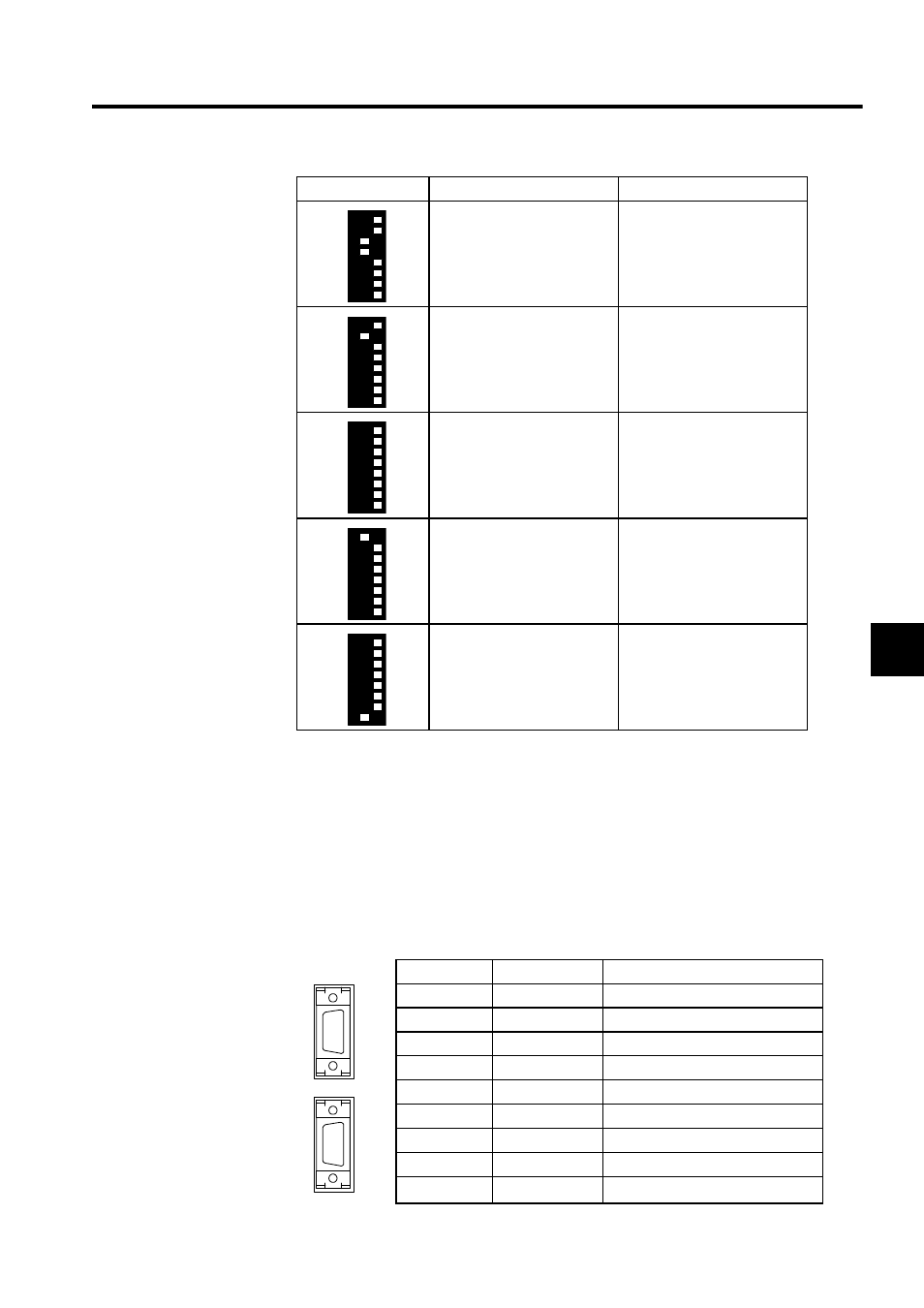
Switch Setting
Function
Explanation
Memory clear
Initializes the CPU Module.
Perform this operation when
starting the system.
Program run
Runs the user program.
Normally, this setting is used
during system operation.
Program stop
Stops the user program.
Local reset
Resets only the CPU Module.
(Other Modules will not be
reset.)
Master reset
Resets all Modules.
Table 5.3 MEMOBUS Port Layout and Signal Names
Pin
Abbreviation
Signal Name
1
FG
Protective ground
2
TXD
Transmitting data
3
RXD
Receiving data
4
RTS
Request to send
5
CTS
Clear to send
6
DSR
Data set ready
7
GND
Signal ground
8
−
9
DTR
Data terminal ready
PORT2
PORT1