Yaskawa MP920 User's Manual Design User Manual
Page 441
9 Multi-CPU System
9.2.2 Setup Procedure Using the MPE720
9-14
This setting must be made only for the CPU Module to read the data. If the common
memory assignments are made for both CPU Modules, the shared memory function will
not be executed correctly.
• Setting Example
6. Module Configuration Definitions
Log on to CPU Module 1 in offline mode from the MPE720 to define the module con-
figuration. Once the settings for CPU Module 1 are made and saved, the settings will be
copied in the file of CPU Module 2. Simply check the copied settings for CPU Module
2, and then make settings for other Modules in the configuration.
a) Setting Two CPU Modules
Set CPU Module 1 in slot 00, and then set CPU Module 2 in slot 02.
HI/LI Settings
Reads the contents of the M registers specified by the other CPU Mod-
ule and writes them to the M registers with the same addresses in this
CPU Module. HI will execute the write during the system I/O process-
ing in the high-speed scan. LI will execute the write during the system
I/O processing in the low-speed scan. Select HI when the user ladder
program is being used in the high-speed scan, and select LI when the
user ladder program is being used in the low-speed scan.
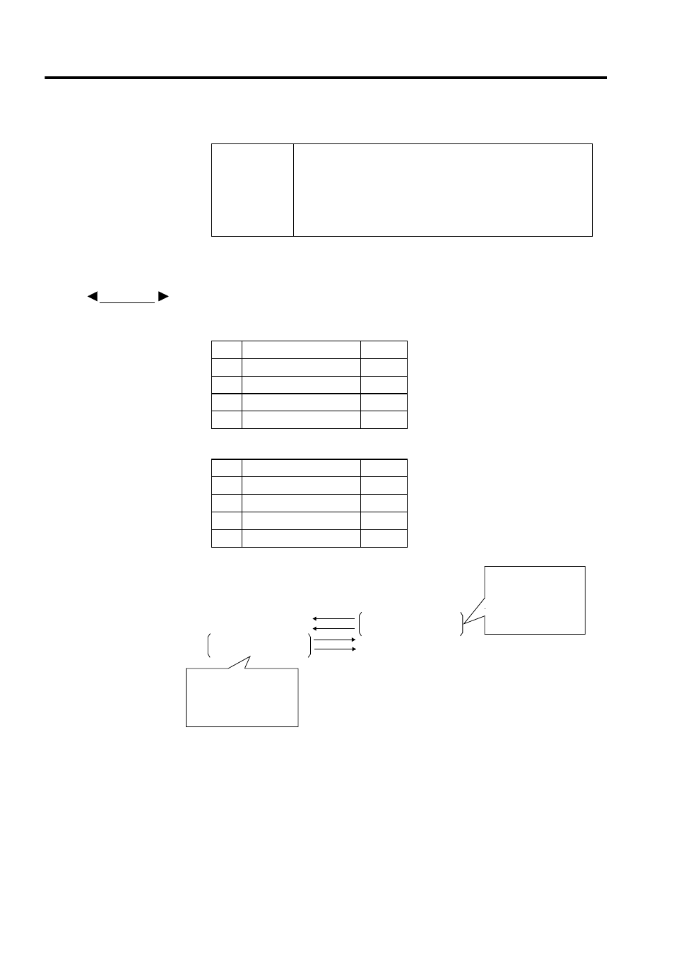
Table 9.5 CPU Module 1
No.
Range
Scan
01
MW00000 to MW00099
HI
02
MW00200 to MW00299
HI
03
04
Table 9.6 CPU Module 2
No.
Range
Scan
01
MW00100 to MW00199
HI
02
MW00300 to MW00399
HI
03
04
Table 9.4 Scan Selection (cont’d)
EXAMPLE
MW00000 to MW00099
MW00200 to MW00299
MW00100 to MW00199
MW00399 to MW00399
MW00000 to MW00099
MW00200 to MW00299
MW00100 to MW00199
MW00399 to MW00399
With the setting example
shown in Table 9.4 and
Table 9.5, the output (HO)
must not be specified for
CPU Module 1.
With the setting
example shown in
Table 9.4 and Table
9.5, the output (HO)
must not be specified
for CPU Module 2.
CPU Module 1
CPU Module 2