Expansion interface module – Yaskawa MP920 User's Manual Design User Manual
Page 48
2 MP920 Specifications and System Configuration
2.1.2 Hardware Specifications
2-22
Expansion Interface Module
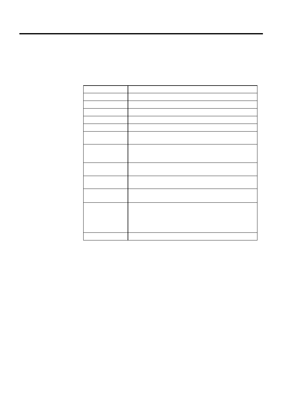
Table 2.20 shows the hardware specifications of the Expansion Interface Module.
Table 2.20 Hardware Specifications of the Expansion Interface Module
Item
Specifications
Name
Expansion Interface Module
Model Number
JEPMC-EX200
Description
EXIOIF
Function
System bus expansion
Supply Voltage
+5 V, 400 mA, power supply from Mounting Base
Interface
GPIP driver (equivalent to SN75160 (TI))
Address bus (30 bits), data (16 bits), control signals, etc.
Rack 1 Recognition
Rack 1 in which the CPU Module is mounted will be automatically
recognized when an extension cable is connected. (The rack is recog-
nized as Rack 1 when no 1N connector is connected.)
Cable Length
Between Racks: 3 m max.
Maximum cable length with 4 Racks used: 5 m
Current
Consumption
580 mA
Indicator
Module status LED indicator
RUN (green)
Setting Switch
SW1: DIP switch
−
MODE
−
−
Dimensions (mm)
40
× 130 × 105 (W × H × D)