Yaskawa MP920 User's Manual Design User Manual
Page 282
5.5 Motion Modules
5-87
5
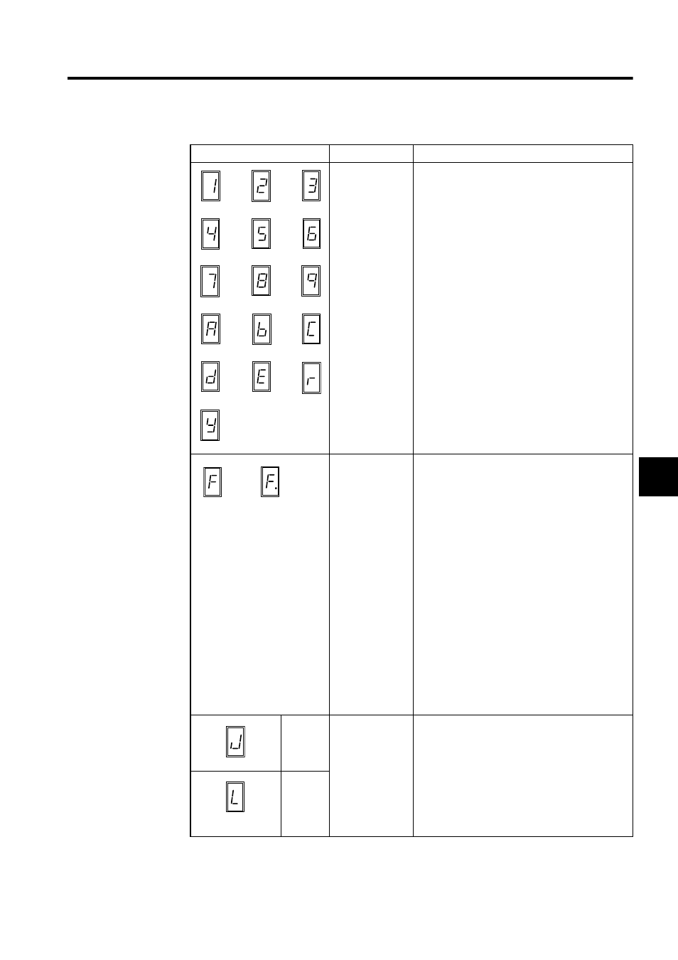
Normal
operation
One of Servo Module numbers 1 to 16 will be dis-
played. The Servo Module is operating normally
and there is no error or alarm.
Serious fault
A two-digit error code appears following F.
Examples:
F
→ 0
→
1: Watchdog timeout error
F
→ 0 → 2: Synchronization error
F
→ 4 → 1: ROM diagnostic error
F
→ 4 → 2: RAM diagnostic error
F
→ 4 → 3: Shared memory diagnostic error
F
→ 4 → 4: Built-in CPU timer diagnostic error
F
→ 4 → 5: Timer diagnostic error
F
→ 4 → 6: NVRAM read error
F
→ 4 → 7: NVRAM write error
F
→ 4 → 8: Illegal general instruction interrupt
F
→ 4 → 9: Illegal slot instruction interrupt
F
→ 5 → 0: CPU address error interrupt
F
→ 5 → 1: DMA address error interrupt
F
→ 5 → 2: User break interrupt
F
→ 5 → 3: Trap instruction interrupt
F
→ 5 → 4: UPD71054 diagnostic error
Axis 1
Alarm
(SVRDY: ON)
Error
(SVRDY: OFF)
Check the contents of IW
00 + the axis offset to
determine which of the items shown below is the
cause of the problem.
• Alarm
Deviation error
Setting parameter setting error
• Error
Fixed parameter setting error
Absolute encoder interface error
Axis 2
(cont’d)
Display
Category
Meaning
or
followed by error code