5 mp920 module definitions, 1 mp920 module configuration – Yaskawa MP900 Series Machine Controller for Standard Operation User Manual
Page 114
3.5 MP920 Module Definitions
3-19
3
3.5 MP920 Module Definitions
This section explains how to select Modules that compose the MP920 Machine Controller and
how to make settings such as disabling I/O registers. After defining the Module configuration
here, make the individual I/O and transmission definitions for each Module.
3.5.1 MP920 Module Configuration
The MP920 is a Building-block Machine Controller and Modules can be assembled as
required with only certain restrictions. Expansion Interface Modules can be used to create a
system with up to 4 racks.
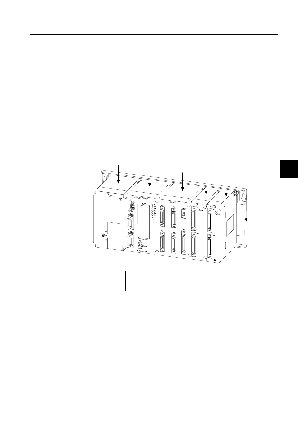
The following diagram shows an example MP920 configuration.
3.5.2 Opening the Module Configuration Definitions Window
Open the following window according to the procedure in 3.2 Basic Module Configuration
Definition Operation.
On the MP920, slots 00 to 08 (with a long rack) on racks 1 to 4, the maximum system con-
figuration, must be set. The first time registration is attempted, all Modules will be UNDE-
FINED, so settings must be made from the CPU Module. For details information concerning
racks and slots, refer to the MP920 User's Manual: Design and Maintenance (SIEZ-C887-
2.1).
Power Supply
Module
The number of Basic Modules can be
increased by mounting an Expansion
Interface Module here and expanding to
another rack.
MP920
CPU Module
SVA-01
Module
DI-01
Module
DO-01
Module
Mounting
Base
(Rack)