Details of trace data definitions – Yaskawa MP900 Series Machine Controller for Standard Operation User Manual
Page 279
System Configuration Definitions
4.5.4 Data Trace Definition Tab Page
4-22
4
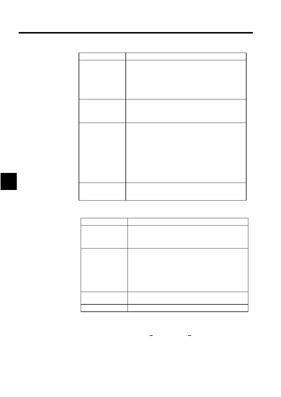
Details of Trace Data Definitions
If the trace data definition is saved with no data entered in the Trace Data Definition field,
the trace definition data for the currently displayed group will be deleted. In effect, this is the
same as deleting it by selecting File (F) and then Delete (D) from the Data Trace Menu.
Trace No. of Times
Input the maximum number of times that the data trace is to be exe-
cuted. Cannot be set when "Program" is selected for the Trace Tim-
ing Box.
If 0 is input, a continuous trace (cyclic trace) will be executed until it
is stopped either manually or by the condition in the Terminate Trig-
ger Condition Box. If 1000 is input, the trace will be executed for
1,000 data samples.
Trigger Condition:
Initiate (Initiate Trigger
Condition)
Input the condition for beginning the data trace. Cannot be set when
"Program" is selected for the Trace Timing Box.
If no condition is input here, then the trace operation must be started
manually.
Trigger Condition:
Terminate 1 or
Terminate 2 (Terminate
Trigger Condition)
Input the condition for stopping the data trace and the number of
traces to be executed after the condition is met. Up to two terminate
trigger conditions can be set. Cannot be set when “Program” is
selected for the Trace Timing Box.
If 0 is input in the Delay Box, the trace will be stopped immediately
when the trigger condition is met. If no terminate trigger condition is
input, the data trace will be executed until it is stopped either manu-
ally or by reaching the number of traces specified in the Trace No. of
Times Box. If there are two conditions set for the terminate trigger
condition, then the data trace will be stopped when either of those
conditions is met.
Trace Data Definition
Input the register numbers, drawing numbers, scale conversion val-
ues, or comments that are to be traced. A maximum of 16 items can
be specified.
Setting Item
Details
REG (Register
Number)
Input the numbers of the registers to be traced. The types of registers
that can be input are S, O, M, and D registers. Depending on the for-
mat of the register, the data to be traced can be integer data, double-
length integer data, or bit data.
DWG (Drawing
Number)
If the register number to be traced is a D register (i.e., if a D register
is input in the REG Box), then input a D register drawing number.
For a motion program, input a motion program drawing number
(MPxxxx). If the register number is not a D register, there is no need
to input anything here. D registers in different scans cannot be speci-
fied at the same time. Also, the data trace can be executed only when
the scan level of the D registers to be traced is the same as the scan
level specified in the Trace Timing Box.
SCALE (Scale
Conversion Value)
Input the scale conversion value for the traced data. This value will
be the amplitude when the trace data is displayed in a graph.
Comment
Input a comment for the register to be traced, up to 32 characters.
Setting Item
Details