Yaskawa MP900 Series Machine Controller for Standard Operation User Manual
Page 162
3.5 MP920 Module Definitions
3-67
3
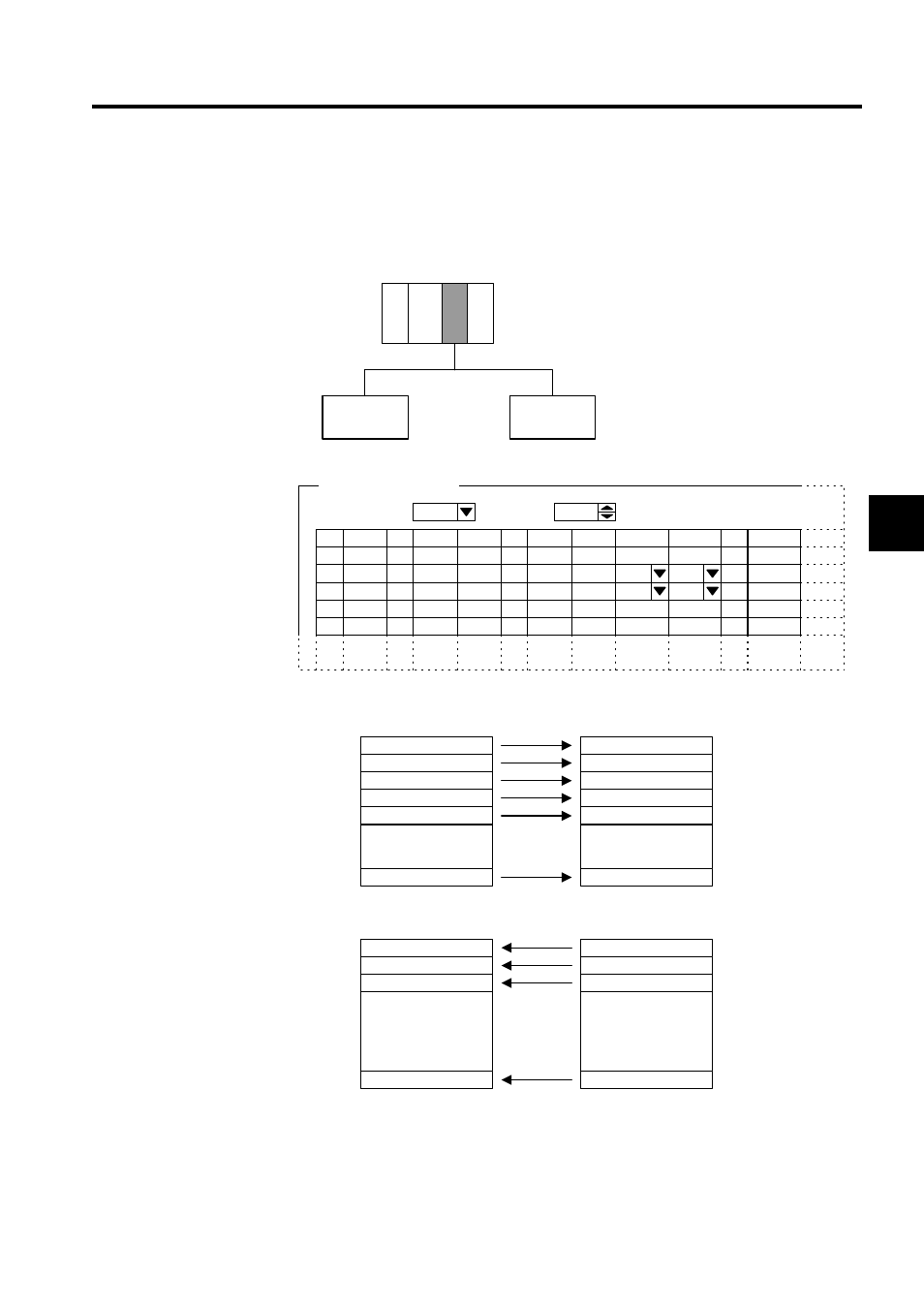
3. Example of Master I/O Allocations
Make the settings as shown in the following diagram to use the 260IF as a DeviceNet
master with MAC ID = 5, to send data to a 2-byte Output Module with MAC ID =2 and
receive data from a 1-byte Input Module with a MAC ID = 3.
PS MP920 260IF
MAC ID = 02
MAC ID = 03
Node address #05
(MAC ID = 05)
Node address
#02
Node address
#03
D
SCAN
01
MAC ID
02
03
・・・
・・・
04
D
INPUT
IW1101
OUTPUT
OW1100
BSIZE
2
Low
TYPE
Polled
EM
BSIZE
1
MAC ID:
5
Low
Polled
2. I/O Allocation Settings
Master/slave:
Master
Comment
・
・
・
IB11021
IB11022
IB11023
IB11024
IB11025
・
・
・
IB110028
・
・
・
・
・
・
・
・
・
OB11000
OB11001
OB11002
・
・
・
OB1100F
Node address #03
(MAC ID = 03)
Node address #05
(MAC ID = 05)
Input relays
Input contact signal 1
Input contact signal 2
Input contact signal 3
Input contact signal 4
Input contact signal 5
Input contact signal 8
Node address #02
(MAC ID = 02)
Output coils
Output contact signal 1
Output contact signal 2
Output contact signal 3
Output contact signal 16