Setting configuration rack information – Yaskawa MP900 Series Machine Controller for Standard Operation User Manual
Page 116
3.5 MP920 Module Definitions
3-21
3
The Power Supply Module is required, even though it is not displayed in the Module Con-
figuration Definitions Window.
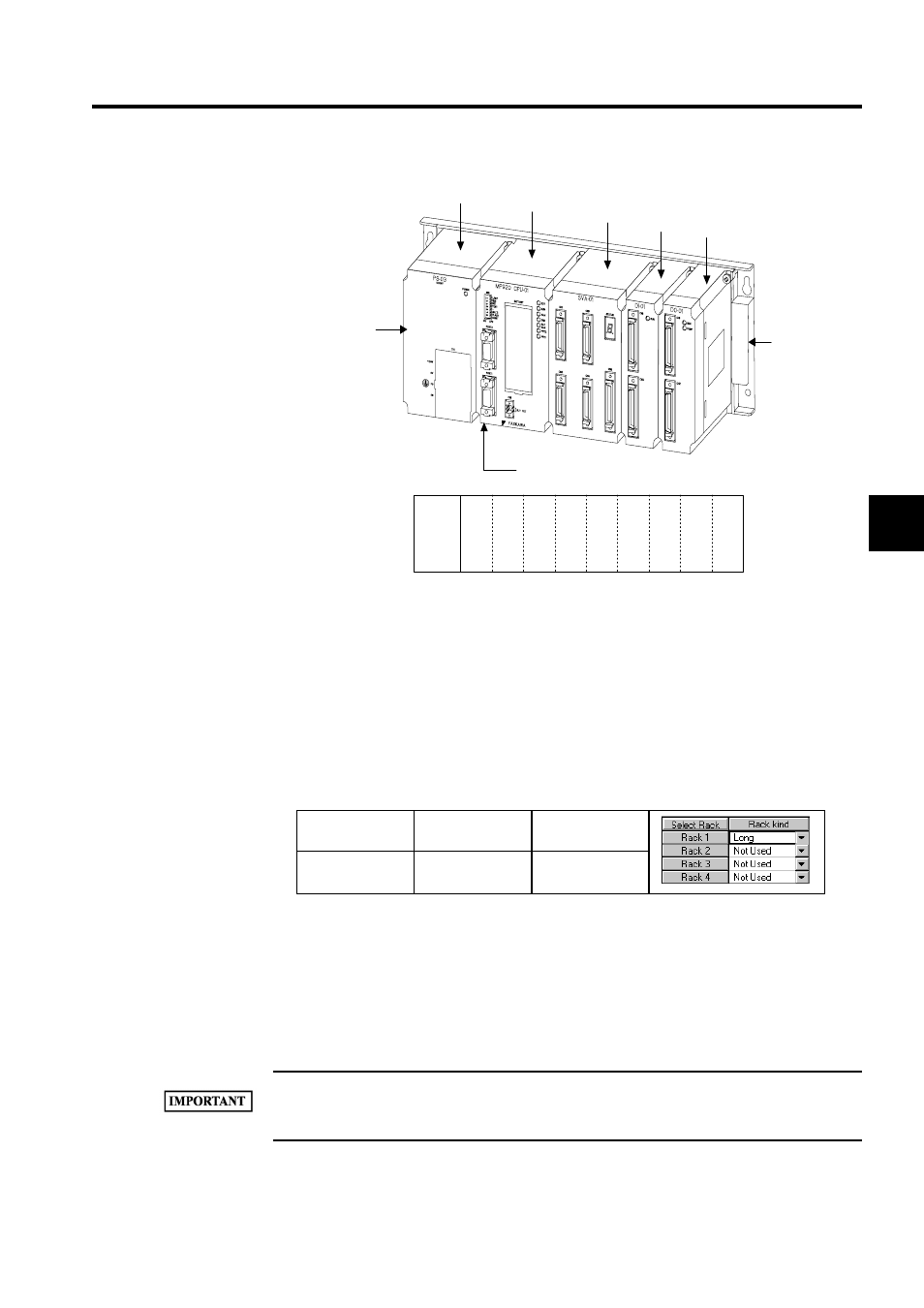
Setting Configuration Rack Information
Select the kind of rack to be connected to the Module. A maximum of 4 racks can be con-
nected to the MP920. Short racks have 6 slots and long racks have 9 slots. Set the configura-
tion rack information depending on the system configuration in use.
Rack numbers must be consecutive. For example, it is not possible to jump from rack 1 to
rack 3. When setting two or more racks from rack 1 to rack 4, always define an EXIOIF
Module on each rack.
For example, if Modules from slot 8 onwards are defined using the long configuration, and
this is changed to the short configuration, Modules from slot 8 onwards cannot be edited.
For single CPU configuration and multiple CPU configuration, select "long" or "short."
If changing racks in online mode, execute the change while Machine Controller operation is stopped.
Refer to 2.1.8 Switching the CPU Status for the procedure to stop the Machine Controller.
Machine
Controller
Maximum No. of
Racks
Remarks
MP920
4
PS
Slot
0
1
2
3
4
5
6
7
8
The Power
Supply Module
is mounted on
the left side of
each rack.
(Slot numbers on a long rack)
Slots are numbered 0, 1, 2, ... from the left
following the Power Supply Module.
Mounting Base
(Rack)
Power Supply
Module
MP920 CPU
Module
SVA-01
Module
DI-01
Module
DO-01
Module