Yaskawa MP900 Series Machine Controller for Standard Operation User Manual
Page 371
Ladder Logic Programming
7.1.1 Ladder Programming System
7-4
7
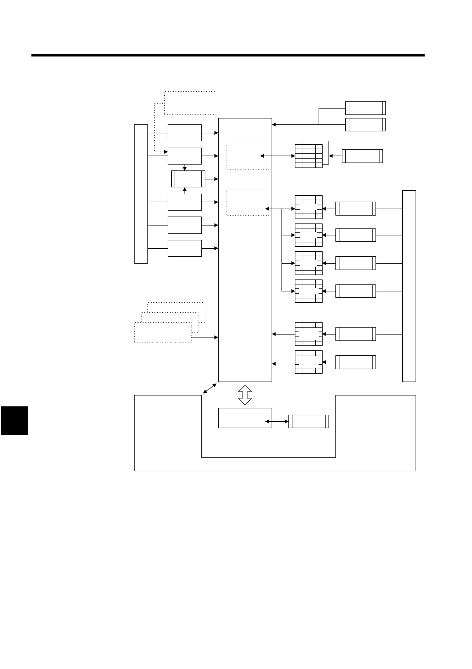
Based on the above diagram, the following items are described in this chapter.
• Setting properties
• Creating parent and main programs
• Creating table programs
• Creating tuning panels
• Creating C registers
• Creating table data
• Tools
TBLxxx
QTBLxx
XCALL xxxx
・・・
MCTBL
IOTBL
ILKTBL
ASMTBL
・・・
Open
I,Q,M,D
Symbol/register
input
mode
Automatically
registered
Configuration
definitions
Proper
ties
Symbol
definitions
Comment
list
# register list
Update
history
I/O
definitions
(Functions only)
SFC action box
SFC time chart
SFC flowchart
Refer to ladder pro-
gramming manual.
Drawings/Func-
tions
Table data instruc-
tions
Table program
execution
instructions
Ladder
diagrams
Shared
Parent
diagram
Main
program
Table data
definitions
Constant tables
(M resister)
I/O conversion
tables
Interlock
tables
Component
assembly tables
Constant tables
(# resister)
C constant
tables
Ta
b
le pr
ograms
Not
shared
Shared
# constant
tables
C constant
tables
Register lists
Cross-references
Registers
Tuning panels
Disable coil lists
Comment lists
Register number
conversion
Tools