19 svb motion parameters settings, Outline of svb motion parameter settings – Yaskawa MP900 Series Machine Controller for Standard Operation User Manual
Page 193
Module Configuration Definitions
3.5.19 SVB Motion Parameters Settings
3-98
3
4 The Error Detection Message Box is displayed if the data was not saved successfully. Refer to Appen-
dix A Error Messages, eliminate the cause of the error, and save the data again.
3.5.19 SVB Motion Parameters Settings
This section explains how to set the motion parameters for the SVB-01 Module.
The SVB Module is equipped with a MECHATROLINK interface, and can connect to a
maximum of 14 SERVOPACKs and I/O devices that are MECHATROLINK-compatible.
SVB Module definitions are set on two levels: MECHATROLINK and the motion parame-
ters. The required settings will differ depending on the device connected using MECHA-
TROLINK.
First, define the MECHATROLINK interface according to 3.5.20 MECHATROLINK Defini-
tions. The Motion Parameters Window cannot be opened without the MECHATROLINK
definitions first being set.
Outline of SVB Motion Parameter Settings
The SVB-01 Module has a single MECHATROLINK connector and can control up to 14
Module Devices with MECHATROLINK interfaces.
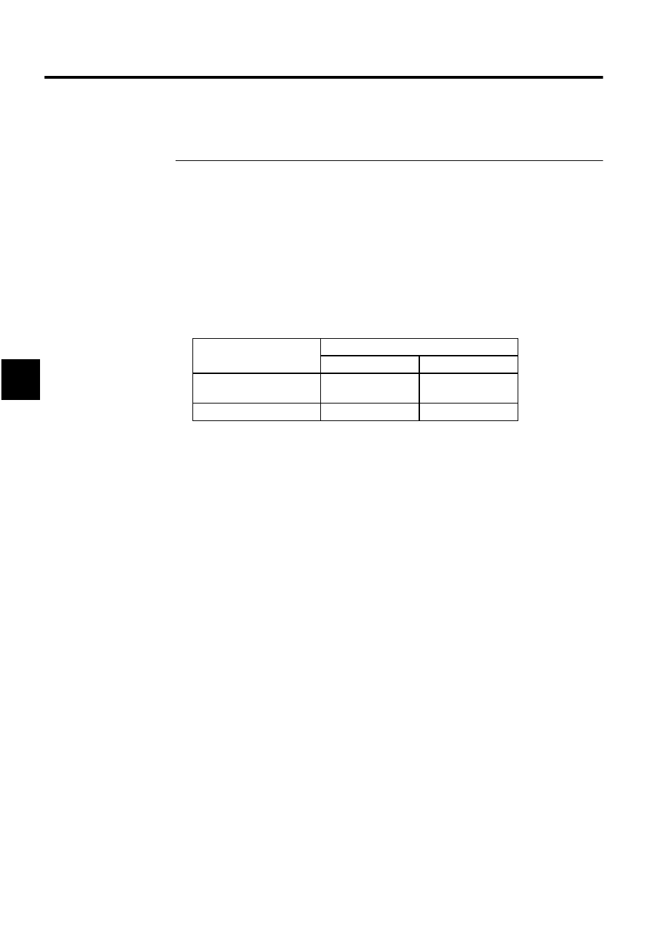
To set the motion parameters, the required data must be set (or referenced) in four tab pages:
the Fixed Parameters Tab, Set Up Parameters Tab, SERVOPACK Tab, and Monitor
Tab.
MECHATROLINK Device
SERVOPACK
I/O Device
MECHATROLINK
Definitions
Yes
Yes
Motion Parameter Settings Yes
No